HP Visualize b180L hp Visualize workstation b132L, b132L plus, b160L, b180L se - Page 152
Removing the CPU Board
 |
View all HP Visualize b180L manuals
Add to My Manuals
Save this manual to your list of manuals |
Page 152 highlights
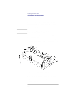
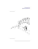
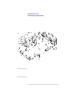
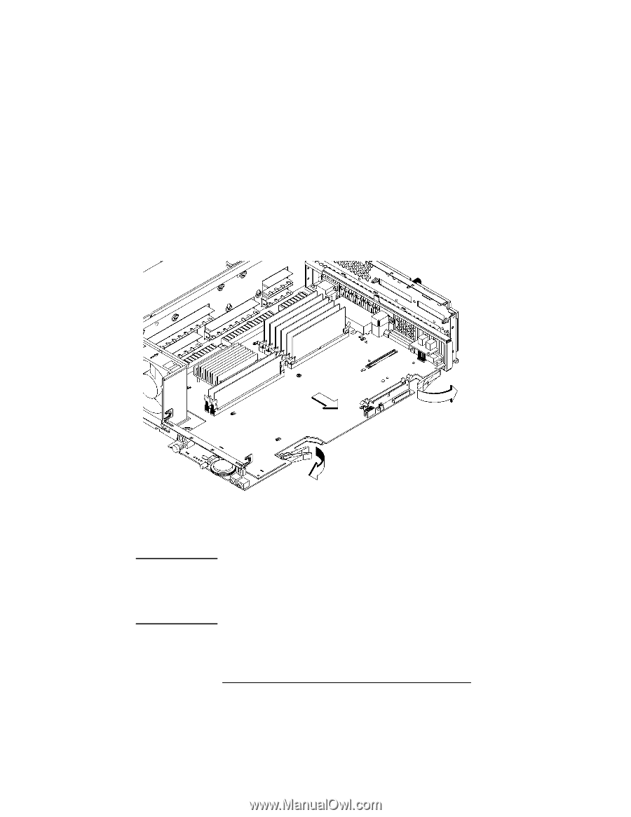
Field Replaceable Units FRU Removal and Replacement Removing the CPU Board Perform the following steps to remove the CPU board from the main tray: 1 Pull the two ejector handles at the same time, as shown in Figure 40. Figure 40 NOTICE: Removing the CPU Board 2 Slide the CPU board out of the main tray. Before installing a CPU board assembly, swing the card ejectors out to the fully open position. After sliding the CPU assembly into place, push firmly on the ejector handles to fully seat the CPU board connector in the backplane. 130
-
 1
1 -
2
-
3
-
4
-
5
-
6
-
7
-
8
-
9
-
10
-
11
-
12
-
13
-
14
-
15
-
16
-
17
-
18
-
19
-
20
-
21
-
22
-
23
-
24
-
25
-
26
-
27
-
28
-
29
-
30
-
31
-
32
-
33
-
34
-
35
-
36
-
37
-
38
-
39
-
40
-
41
-
42
-
43
-
44
-
45
-
46
-
47
-
48
-
49
-
50
-
51
-
52
-
53
-
54
-
55
-
56
-
57
-
58
-
59
-
60
-
61
-
62
-
63
-
64
-
65
-
66
-
67
-
68
-
69
-
70
-
71
-
72
-
73
-
74
-
75
-
76
-
77
-
78
-
79
-
80
-
81
-
82
-
83
-
84
-
85
-
86
-
87
-
88
-
89
-
90
-
91
-
92
-
93
-
94
-
95
-
96
-
97
-
98
-
99
-
100
-
101
-
102
-
103
-
104
-
105
-
106
-
107
-
108
-
109
-
110
-
111
-
112
-
113
-
114
-
115
-
116
-
117
-
118
-
119
-
120
-
121
-
122
-
123
-
124
-
125
-
126
-
127
-
128
-
129
-
130
-
131
-
132
-
133
-
134
-
135
-
136
-
137
-
138
-
139
-
140
-
141
-
142
-
143
-
144
-
145
-
146
-
 147
147 -
 148
148 -
 149
149 -
 150
150 -
 151
151 -
 152
152 -
 153
153 -
 154
154 -
 155
155 -
 156
156 -
 157
157 -
158
-
159
-
160
-
161
-
162
-
163
-
164
-
165
-
166
-
167
-
168
-
169
-
170
-
171
-
172
-
173
-
174
-
175
-
176
-
177
-
178
-
179
-
180
-
181
-
182
-
183
-
184
-
185
-
186
-
187
-
188
-
189
-
190
-
191
-
192
-
193
-
194
-
195
-
196
-
197
-
198
-
199
-
200
-
201
-
202
-
203
-
204
-
205
-
206
-
207
-
208
-
209
-
210
-
211
-
212
-
213
-
214
-
215
-
216
-
217
-
218
-
219
-
220
-
221
-
222
-
223
-
224
-
225
-
226
-
227
-
228
-
229
-
230
-
231
-
232
-
233
-
234
-
235
-
236
-
237
-
238
-
239
-
240
-
241
-
242
 |
 |
Field Replaceable Units
FRU Removal and Replacement
130
Removing the CPU Board
Perform the following steps to remove the CPU board
from the main tray:
1
Pull the two ejector handles at the same time, as shown
in Figure 40.
Figure 40
Removing the CPU Board
2
Slide the CPU board out of the main tray.
NOTICE:
Before installing a CPU board assembly, swing the
card ejectors out to the fully open position. After
sliding the CPU assembly into place, push firmly
on the ejector handles to fully seat the CPU board
connector in the backplane.