HP Visualize b180L hp Visualize workstation b132L, b132L plus, b160L, b180L se - Page 171
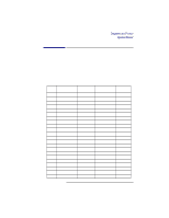
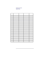
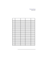
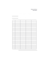
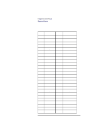
Table 18 lists the pinouts for the Backplane to EISA, Slot connector for rows F, B, E, and A. Table
 |
View all HP Visualize b180L manuals
Add to My Manuals
Save this manual to your list of manuals |
Page 171 highlights
Diagrams and Pinouts System Power Table 18 lists the pinouts for the Backplane to EISA Slot connector for rows F, B, E, and A. Table 18 lists the pinouts for rows H, D, G, and C. NOTE: Table 18 Rows A, C, F, and H are Upper (ISA) contacts. Rows B, D, E, and G are Lower (EISA) contacts. Backplane EISA Slot Connector (Rows F, B, E, and A) Pin Row F 1 GND 2 +5V 3 +5V 4 X 5 X 6 ACCESS KEY 7 X 8 X 9 +12V 10 M-IO 11 LOCK 12 RESERVED 13 GND 14 RESERVED 15 BE 16 ACCESS KEY 17 BE 18 BE 19 GND 20 +5V 21 LA Row B GND RESDRV +5V IRQ -5V DRQ -12V NOWS +12V GND SMWTC SMRDC IOWC IORC DAK DRQ DAK DRQ REFRESH BCLK IRQ Row E CMD START EXRDY EX32 GND ACCESS KEY EX16 SLBURST MSBURST W-R GND RESERVED RESERVED RESERVED GND ACCESS KEY BE LA GND LA LA Row A IOCHK D D D D D D D D CHRDY AENx SA SA SA SA SA SA SA SA SA SA 149
-
 1
1 -
2
-
3
-
4
-
5
-
6
-
7
-
8
-
9
-
10
-
11
-
12
-
13
-
14
-
15
-
16
-
17
-
18
-
19
-
20
-
21
-
22
-
23
-
24
-
25
-
26
-
27
-
28
-
29
-
30
-
31
-
32
-
33
-
34
-
35
-
36
-
37
-
38
-
39
-
40
-
41
-
42
-
43
-
44
-
45
-
46
-
47
-
48
-
49
-
50
-
51
-
52
-
53
-
54
-
55
-
56
-
57
-
58
-
59
-
60
-
61
-
62
-
63
-
64
-
65
-
66
-
67
-
68
-
69
-
70
-
71
-
72
-
73
-
74
-
75
-
76
-
77
-
78
-
79
-
80
-
81
-
82
-
83
-
84
-
85
-
86
-
87
-
88
-
89
-
90
-
91
-
92
-
93
-
94
-
95
-
96
-
97
-
98
-
99
-
100
-
101
-
102
-
103
-
104
-
105
-
106
-
107
-
108
-
109
-
110
-
111
-
112
-
113
-
114
-
115
-
116
-
117
-
118
-
119
-
120
-
121
-
122
-
123
-
124
-
125
-
126
-
127
-
128
-
129
-
130
-
131
-
132
-
133
-
134
-
135
-
136
-
137
-
138
-
139
-
140
-
141
-
142
-
143
-
144
-
145
-
146
-
147
-
148
-
149
-
150
-
151
-
152
-
153
-
154
-
155
-
156
-
157
-
158
-
159
-
160
-
161
-
162
-
163
-
164
-
165
-
 166
166 -
 167
167 -
 168
168 -
 169
169 -
 170
170 -
 171
171 -
 172
172 -
 173
173 -
 174
174 -
 175
175 -
 176
176 -
177
-
178
-
179
-
180
-
181
-
182
-
183
-
184
-
185
-
186
-
187
-
188
-
189
-
190
-
191
-
192
-
193
-
194
-
195
-
196
-
197
-
198
-
199
-
200
-
201
-
202
-
203
-
204
-
205
-
206
-
207
-
208
-
209
-
210
-
211
-
212
-
213
-
214
-
215
-
216
-
217
-
218
-
219
-
220
-
221
-
222
-
223
-
224
-
225
-
226
-
227
-
228
-
229
-
230
-
231
-
232
-
233
-
234
-
235
-
236
-
237
-
238
-
239
-
240
-
241
-
242
 |
 |
