HP Visualize b180L hp Visualize workstation b132L, b132L plus, b160L, b180L se - Page 154
Grasp the EGRAM module from the sides and pull, it straight up to disconnect it from the CPU board,
 |
View all HP Visualize b180L manuals
Add to My Manuals
Save this manual to your list of manuals |
Page 154 highlights
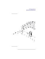
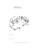
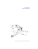
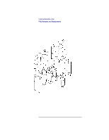
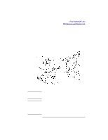
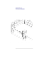
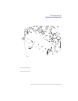
NOTICE: Field Replaceable Units FRU Removal and Replacement 2 Grasp the EGRAM module from the sides and pull it straight up to disconnect it from the CPU board connector, as shown in Figure 41. When replacing the EGRAM module make sure that its connector is correctly aligned with the connector on the CPU board and press down firmly to make sure that it is fully connected. Press down on the corners of the module to make sure that the standoffs are fully engaged. If you are moving the EGRAM module to a new CPU board assembly, from the underside of the CPU board assembly use a pair of needle-nose pliers to squeeze the tabs on the standoffs and push them out of the CPU board. Transfer the standoffs to the new CPU board. 132
-
 1
1 -
2
-
3
-
4
-
5
-
6
-
7
-
8
-
9
-
10
-
11
-
12
-
13
-
14
-
15
-
16
-
17
-
18
-
19
-
20
-
21
-
22
-
23
-
24
-
25
-
26
-
27
-
28
-
29
-
30
-
31
-
32
-
33
-
34
-
35
-
36
-
37
-
38
-
39
-
40
-
41
-
42
-
43
-
44
-
45
-
46
-
47
-
48
-
49
-
50
-
51
-
52
-
53
-
54
-
55
-
56
-
57
-
58
-
59
-
60
-
61
-
62
-
63
-
64
-
65
-
66
-
67
-
68
-
69
-
70
-
71
-
72
-
73
-
74
-
75
-
76
-
77
-
78
-
79
-
80
-
81
-
82
-
83
-
84
-
85
-
86
-
87
-
88
-
89
-
90
-
91
-
92
-
93
-
94
-
95
-
96
-
97
-
98
-
99
-
100
-
101
-
102
-
103
-
104
-
105
-
106
-
107
-
108
-
109
-
110
-
111
-
112
-
113
-
114
-
115
-
116
-
117
-
118
-
119
-
120
-
121
-
122
-
123
-
124
-
125
-
126
-
127
-
128
-
129
-
130
-
131
-
132
-
133
-
134
-
135
-
136
-
137
-
138
-
139
-
140
-
141
-
142
-
143
-
144
-
145
-
146
-
147
-
148
-
 149
149 -
 150
150 -
 151
151 -
 152
152 -
 153
153 -
 154
154 -
 155
155 -
 156
156 -
 157
157 -
 158
158 -
 159
159 -
160
-
161
-
162
-
163
-
164
-
165
-
166
-
167
-
168
-
169
-
170
-
171
-
172
-
173
-
174
-
175
-
176
-
177
-
178
-
179
-
180
-
181
-
182
-
183
-
184
-
185
-
186
-
187
-
188
-
189
-
190
-
191
-
192
-
193
-
194
-
195
-
196
-
197
-
198
-
199
-
200
-
201
-
202
-
203
-
204
-
205
-
206
-
207
-
208
-
209
-
210
-
211
-
212
-
213
-
214
-
215
-
216
-
217
-
218
-
219
-
220
-
221
-
222
-
223
-
224
-
225
-
226
-
227
-
228
-
229
-
230
-
231
-
232
-
233
-
234
-
235
-
236
-
237
-
238
-
239
-
240
-
241
-
242
 |
 |

Field Replaceable Units
FRU Removal and Replacement
132
2
Grasp the EGRAM module from the sides and pull
it straight up to disconnect it from the CPU board
connector
, as shown in Figure 41.
NOTICE:
When replacing the EGRAM module make sure
that its connector is correctly aligned with the
connector on the CPU board and press down firmly
to make sure that it is fully connected. Press down
on the corners of the module to make sure that the
standoffs are fully engaged.
If you are moving the EGRAM module to a new
CPU board assembly, from the underside of the
CPU board assembly use a pair of needle-nose
pliers to squeeze the tabs on the standoffs and push
them out of the CPU board. Transfer the standoffs
to the new CPU board.