HP Visualize b180L hp Visualize workstation b132L, b132L plus, b160L, b180L se - Page 191
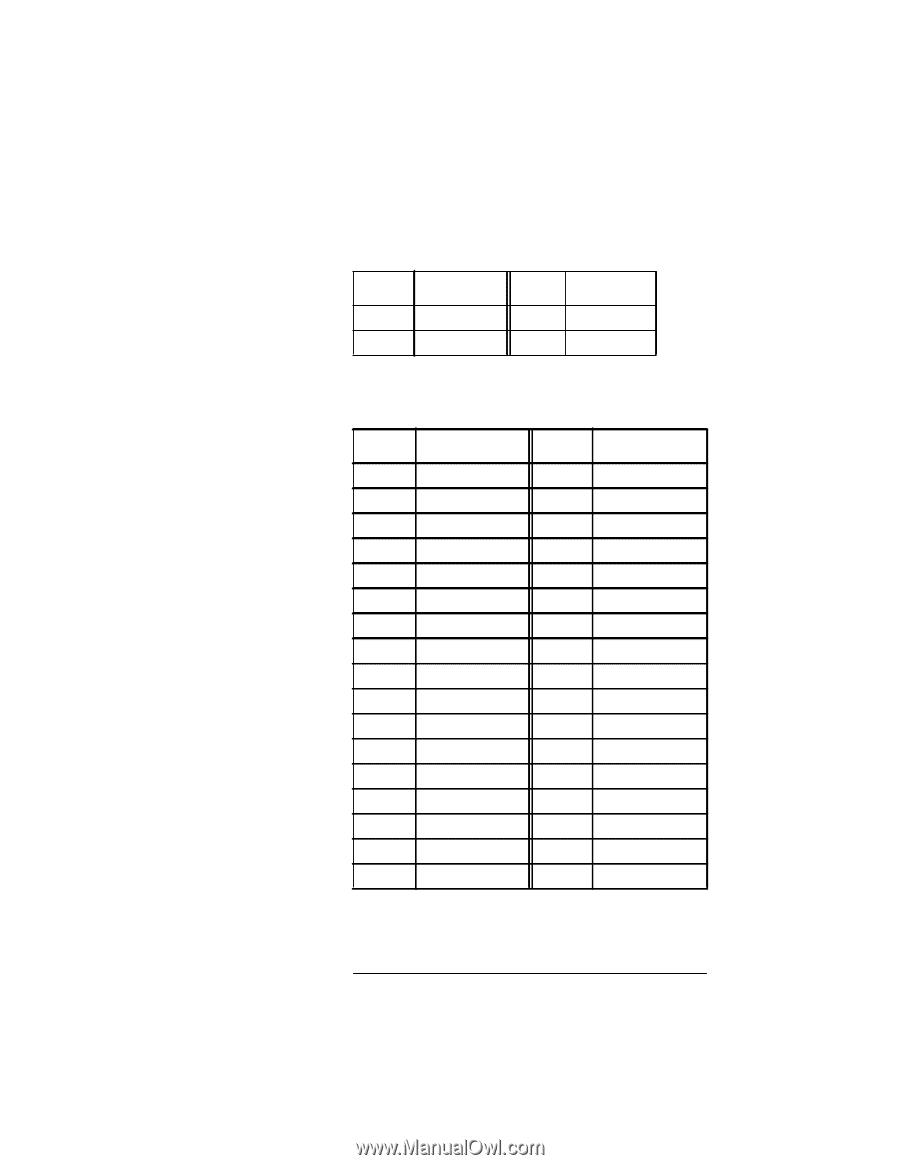
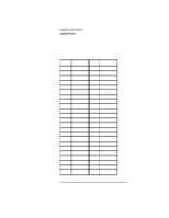
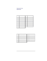
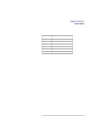
Table 34 lists the pinouts for the SGRAM connector.
 |
View all HP Visualize b180L manuals
Add to My Manuals
Save this manual to your list of manuals |
Page 191 highlights
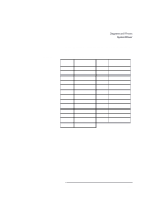
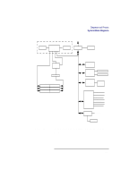
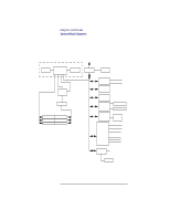
Table 33 Table 34 Diagrams and Pinouts System Power Single-Ended SCSI Connector Pinouts Pin Description Pin Description 24 Ground 49 25 Ground 50 REQ IO Table 34 lists the pinouts for the SGRAM connector. EGRAM Connector Pin Description Pin Description 1 Audio Out, Right 18 USB/1394 Sheild 2 Audio Out, Left 19 P1394 Return 3 Audio Out, Ret 20 P1394 Power 4 Sync Return 21 Audio In, Left 5 Horizontal Sync 22 Audio In, Right 6 Vertical Sync 23 Audio In, Return 7 Reserved 24 Stereo Sync 8 Reserved 25 DDC Return 9 P1394, A- 26 DDC Data 10 P1394, A+ 27 DDC Clock 11 Power Charge + 28 +5 VDC 12 Power Charge - 29 P1394 B+ 13 Video In, Y 30 P1394 B- 14 Video In, Return C1 Red Video Output 15 Video In, C C2 Green Video Output 16 USB+ C3 Pixel Clock Output 17 USB- C4 Blue Video Output 169
-
 1
1 -
2
-
3
-
4
-
5
-
6
-
7
-
8
-
9
-
10
-
11
-
12
-
13
-
14
-
15
-
16
-
17
-
18
-
19
-
20
-
21
-
22
-
23
-
24
-
25
-
26
-
27
-
28
-
29
-
30
-
31
-
32
-
33
-
34
-
35
-
36
-
37
-
38
-
39
-
40
-
41
-
42
-
43
-
44
-
45
-
46
-
47
-
48
-
49
-
50
-
51
-
52
-
53
-
54
-
55
-
56
-
57
-
58
-
59
-
60
-
61
-
62
-
63
-
64
-
65
-
66
-
67
-
68
-
69
-
70
-
71
-
72
-
73
-
74
-
75
-
76
-
77
-
78
-
79
-
80
-
81
-
82
-
83
-
84
-
85
-
86
-
87
-
88
-
89
-
90
-
91
-
92
-
93
-
94
-
95
-
96
-
97
-
98
-
99
-
100
-
101
-
102
-
103
-
104
-
105
-
106
-
107
-
108
-
109
-
110
-
111
-
112
-
113
-
114
-
115
-
116
-
117
-
118
-
119
-
120
-
121
-
122
-
123
-
124
-
125
-
126
-
127
-
128
-
129
-
130
-
131
-
132
-
133
-
134
-
135
-
136
-
137
-
138
-
139
-
140
-
141
-
142
-
143
-
144
-
145
-
146
-
147
-
148
-
149
-
150
-
151
-
152
-
153
-
154
-
155
-
156
-
157
-
158
-
159
-
160
-
161
-
162
-
163
-
164
-
165
-
166
-
167
-
168
-
169
-
170
-
171
-
172
-
173
-
174
-
175
-
176
-
177
-
178
-
179
-
180
-
181
-
182
-
183
-
184
-
185
-
 186
186 -
 187
187 -
 188
188 -
 189
189 -
 190
190 -
 191
191 -
 192
192 -
 193
193 -
 194
194 -
 195
195 -
 196
196 -
197
-
198
-
199
-
200
-
201
-
202
-
203
-
204
-
205
-
206
-
207
-
208
-
209
-
210
-
211
-
212
-
213
-
214
-
215
-
216
-
217
-
218
-
219
-
220
-
221
-
222
-
223
-
224
-
225
-
226
-
227
-
228
-
229
-
230
-
231
-
232
-
233
-
234
-
235
-
236
-
237
-
238
-
239
-
240
-
241
-
242
 |
 |