HP Visualize b180L hp Visualize workstation b132L, b132L plus, b160L, b180L se - Page 56
FRU Configurations
 |
View all HP Visualize b180L manuals
Add to My Manuals
Save this manual to your list of manuals |
Page 56 highlights
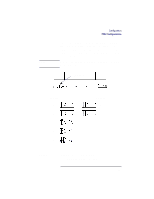
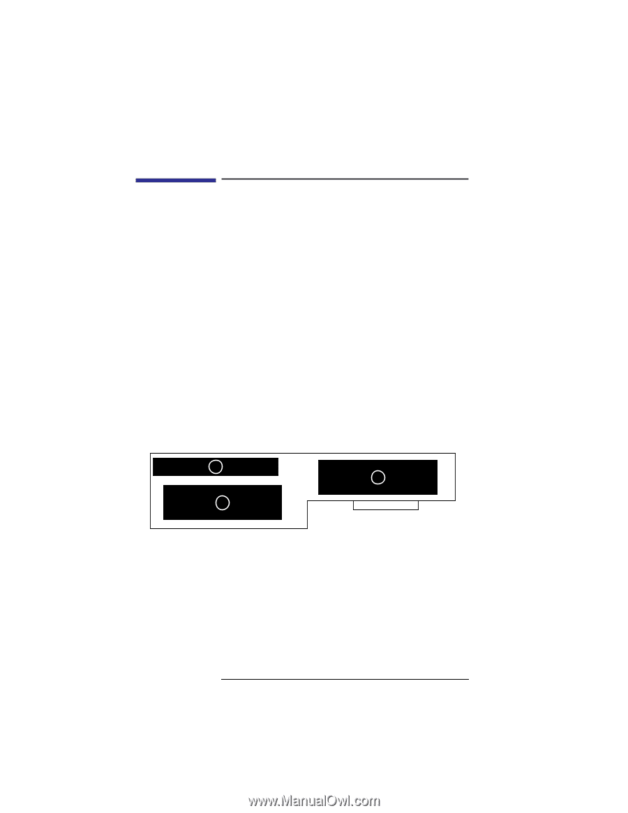
Configuration FRU Configurations FRU Configurations This section provides information for setting up or changing the configuration of the system Field Replaceable Units (FRUs). Internal Storage Configurations Each storage device is restricted as to where in the storage tray it may be installed. Before installing a storage device, use Figure 3 and Table 5 to determine which disk tray position is correct for your device. Figure 3 shows the storage device positions in the disk tray. Table 5 lists what devices are supported in the different disk tray positions. The numbers in the left column of Table 7 refer to the position numbers in Figure 3. 3 1 2 Figure 3 Disk Tray Positions 34
-
 1
1 -
2
-
3
-
4
-
5
-
6
-
7
-
8
-
9
-
10
-
11
-
12
-
13
-
14
-
15
-
16
-
17
-
18
-
19
-
20
-
21
-
22
-
23
-
24
-
25
-
26
-
27
-
28
-
29
-
30
-
31
-
32
-
33
-
34
-
35
-
36
-
37
-
38
-
39
-
40
-
41
-
42
-
43
-
44
-
45
-
46
-
47
-
48
-
49
-
50
-
 51
51 -
 52
52 -
 53
53 -
 54
54 -
 55
55 -
 56
56 -
 57
57 -
 58
58 -
 59
59 -
 60
60 -
 61
61 -
62
-
63
-
64
-
65
-
66
-
67
-
68
-
69
-
70
-
71
-
72
-
73
-
74
-
75
-
76
-
77
-
78
-
79
-
80
-
81
-
82
-
83
-
84
-
85
-
86
-
87
-
88
-
89
-
90
-
91
-
92
-
93
-
94
-
95
-
96
-
97
-
98
-
99
-
100
-
101
-
102
-
103
-
104
-
105
-
106
-
107
-
108
-
109
-
110
-
111
-
112
-
113
-
114
-
115
-
116
-
117
-
118
-
119
-
120
-
121
-
122
-
123
-
124
-
125
-
126
-
127
-
128
-
129
-
130
-
131
-
132
-
133
-
134
-
135
-
136
-
137
-
138
-
139
-
140
-
141
-
142
-
143
-
144
-
145
-
146
-
147
-
148
-
149
-
150
-
151
-
152
-
153
-
154
-
155
-
156
-
157
-
158
-
159
-
160
-
161
-
162
-
163
-
164
-
165
-
166
-
167
-
168
-
169
-
170
-
171
-
172
-
173
-
174
-
175
-
176
-
177
-
178
-
179
-
180
-
181
-
182
-
183
-
184
-
185
-
186
-
187
-
188
-
189
-
190
-
191
-
192
-
193
-
194
-
195
-
196
-
197
-
198
-
199
-
200
-
201
-
202
-
203
-
204
-
205
-
206
-
207
-
208
-
209
-
210
-
211
-
212
-
213
-
214
-
215
-
216
-
217
-
218
-
219
-
220
-
221
-
222
-
223
-
224
-
225
-
226
-
227
-
228
-
229
-
230
-
231
-
232
-
233
-
234
-
235
-
236
-
237
-
238
-
239
-
240
-
241
-
242
 |
 |
Configuration
FRU Configurations
34
FRU Configurations
This section provides information for setting up or
changing the configuration of the system Field
Replaceable Units (FRUs).
Internal Storage Configurations
Each storage device is restricted as to where in the
storage tray it may be installed. Before installing a
storage device, use Figure 3 and Table 5 to determine
which disk tray position is correct for your device.
Figure 3 shows the storage device positions in the disk
tray. Table 5 lists what devices are supported in the
different disk tray positions. The numbers in the left
column of Table 7 refer to the position numbers in
Figure 3.
Figure 3
Disk Tray Positions
1
2
3