HP Visualize b180L hp Visualize workstation b132L, b132L plus, b160L, b180L se - Page 65
A, 1B, and 2A, 2B. The memory configuration is 32
 |
View all HP Visualize b180L manuals
Add to My Manuals
Save this manual to your list of manuals |
Page 65 highlights
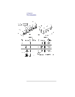
Configuration FRU Configurations Allowable Memory Configurations This workstation has 6 memory slots, labeled 0A, 0B, 1A, 1B, and 2A, 2B. The memory configuration is 32 MB to 768 MB installed in pairs of 16 MB, 32MB, 64 MB, or 128 MB memory modules. Memory modules must be installed in pairs of equal capacity. Always install the largest capacity memory modules in the lowest numbered memory slots and don't skip any numbers. For example, if you have a pair of 16 MB memory modules and a pair of 32 MB memory modules, first install the pair of 32 MB memory modules in slots 0A and 0B, then install the 16 MB modules in slots 1A and 1B. Figure 10 shows the position of the memory connectors on the Main Tray. 43
-
 1
1 -
2
-
3
-
4
-
5
-
6
-
7
-
8
-
9
-
10
-
11
-
12
-
13
-
14
-
15
-
16
-
17
-
18
-
19
-
20
-
21
-
22
-
23
-
24
-
25
-
26
-
27
-
28
-
29
-
30
-
31
-
32
-
33
-
34
-
35
-
36
-
37
-
38
-
39
-
40
-
41
-
42
-
43
-
44
-
45
-
46
-
47
-
48
-
49
-
50
-
51
-
52
-
53
-
54
-
55
-
56
-
57
-
58
-
59
-
 60
60 -
 61
61 -
 62
62 -
 63
63 -
 64
64 -
 65
65 -
 66
66 -
 67
67 -
 68
68 -
 69
69 -
 70
70 -
71
-
72
-
73
-
74
-
75
-
76
-
77
-
78
-
79
-
80
-
81
-
82
-
83
-
84
-
85
-
86
-
87
-
88
-
89
-
90
-
91
-
92
-
93
-
94
-
95
-
96
-
97
-
98
-
99
-
100
-
101
-
102
-
103
-
104
-
105
-
106
-
107
-
108
-
109
-
110
-
111
-
112
-
113
-
114
-
115
-
116
-
117
-
118
-
119
-
120
-
121
-
122
-
123
-
124
-
125
-
126
-
127
-
128
-
129
-
130
-
131
-
132
-
133
-
134
-
135
-
136
-
137
-
138
-
139
-
140
-
141
-
142
-
143
-
144
-
145
-
146
-
147
-
148
-
149
-
150
-
151
-
152
-
153
-
154
-
155
-
156
-
157
-
158
-
159
-
160
-
161
-
162
-
163
-
164
-
165
-
166
-
167
-
168
-
169
-
170
-
171
-
172
-
173
-
174
-
175
-
176
-
177
-
178
-
179
-
180
-
181
-
182
-
183
-
184
-
185
-
186
-
187
-
188
-
189
-
190
-
191
-
192
-
193
-
194
-
195
-
196
-
197
-
198
-
199
-
200
-
201
-
202
-
203
-
204
-
205
-
206
-
207
-
208
-
209
-
210
-
211
-
212
-
213
-
214
-
215
-
216
-
217
-
218
-
219
-
220
-
221
-
222
-
223
-
224
-
225
-
226
-
227
-
228
-
229
-
230
-
231
-
232
-
233
-
234
-
235
-
236
-
237
-
238
-
239
-
240
-
241
-
242
 |
 |

Configuration
FRU Configurations
43
Allowable Memory Configurations
This workstation has 6 memory slots, labeled 0A, 0B,
1A, 1B, and 2A, 2B. The memory configuration is 32
MB to 768 MB installed in pairs of 16 MB, 32MB,
64 MB, or 128 MB memory modules.
Memory modules must be installed in pairs of equal
capacity.
Always install the largest capacity memory modules in
the lowest numbered memory slots and don’t skip any
numbers.
For example, if you have a pair of 16 MB memory
modules and a pair of 32 MB memory modules, first
install the pair of 32 MB memory modules in slots 0A
and 0B, then install the 16 MB modules in slots 1A
and 1B.
Figure 10 shows the position of the memory connec-
tors on the Main Tray.