Netgear GS748Tv5 Software Administration Manual - Page 143
AS Port Settings, To con the 802.1AS port settings, Switching, Advanced, Enable
 |
View all Netgear GS748Tv5 manuals
Add to My Manuals
Save this manual to your list of manuals |
Page 143 highlights
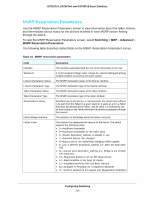
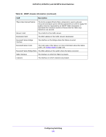
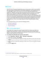
GS716Tv3, GS724Tv4, and GS748Tv5 Smart Switches The following table shows the non-configurable information on the 802.1AS Configuration screen. Table 47. 802.1AS global status Field Description GrandMaster Present Identifies whether Grand Master Clock is present. The default is False. Best Clock Identity The Best Clock Identity detected by this time-aware bridge. Best Clock Priority1 The Priority1 value of the best clock on the switch. Best Clock Priority2 The Priority2 value of the best clock on the switch. Steps to Best Clock The number of links in the path from the Best Clock to this time-aware bridge. If this time-aware bridge is the best, the value is zero. Local Clock Identity The Clock Identity of this time-aware bridge. Last GM Change Timestamp The system time when the most recent grandmaster clock change occurred. 802.1AS Port Settings Use the 802.1AS Port Settings screen to configure and view per-port 802.1AS settings. To configure the 802.1AS port settings: 1. Select Switching > 802.1AS > Advanced > 802.1AS Port Settings. 2. Select the ports to configure. For information about how to select and configure one or more ports, see Configuring Interface Settings on page 28. 3. From the Admin Mode list, select Enable. 4. In the Pdelay Threshhold field, specify the propagation delay threshold on the interface. The threshold determines whether the port is capable of participating in the 802.1AS protocol. If the propagation delay on the interface is above the threshold you configure, the interface is not considered capable of participating in the 802.1AS protocol. The peer delay must be less than the threshold value configured on the interface. The default value is 2500 nanoseconds. The range is 0-1,000,000,000 ns. 5. In the Allowed Lost Responses field, specify the allowed loss response value. If the interface does not receive valid responses to PDELAY_REQ messages above the value of the allowed lost responses, a port is considered to not be exchanging peer delay messages with its neighbor. 6. In the Initial Sync Interval field, specify the desired transmission rate of SYNC messages. This value is the logarithm to the base 2 of the mean-time interval between successive SYNC messages sent on this interface. The configured initial interval becomes the current interval only after the port is initialized or re-initialized for 802.1AS operation. Configuring Switching 143
-
 1
1 -
2
-
3
-
4
-
5
-
6
-
7
-
8
-
9
-
10
-
11
-
12
-
13
-
14
-
15
-
16
-
17
-
18
-
19
-
20
-
21
-
22
-
23
-
24
-
25
-
26
-
27
-
28
-
29
-
30
-
31
-
32
-
33
-
34
-
35
-
36
-
37
-
38
-
39
-
40
-
41
-
42
-
43
-
44
-
45
-
46
-
47
-
48
-
49
-
50
-
51
-
52
-
53
-
54
-
55
-
56
-
57
-
58
-
59
-
60
-
61
-
62
-
63
-
64
-
65
-
66
-
67
-
68
-
69
-
70
-
71
-
72
-
73
-
74
-
75
-
76
-
77
-
78
-
79
-
80
-
81
-
82
-
83
-
84
-
85
-
86
-
87
-
88
-
89
-
90
-
91
-
92
-
93
-
94
-
95
-
96
-
97
-
98
-
99
-
100
-
101
-
102
-
103
-
104
-
105
-
106
-
107
-
108
-
109
-
110
-
111
-
112
-
113
-
114
-
115
-
116
-
117
-
118
-
119
-
120
-
121
-
122
-
123
-
124
-
125
-
126
-
127
-
128
-
129
-
130
-
131
-
132
-
133
-
134
-
135
-
136
-
137
-
 138
138 -
 139
139 -
 140
140 -
 141
141 -
 142
142 -
 143
143 -
 144
144 -
 145
145 -
 146
146 -
 147
147 -
 148
148 -
149
-
150
-
151
-
152
-
153
-
154
-
155
-
156
-
157
-
158
-
159
-
160
-
161
-
162
-
163
-
164
-
165
-
166
-
167
-
168
-
169
-
170
-
171
-
172
-
173
-
174
-
175
-
176
-
177
-
178
-
179
-
180
-
181
-
182
-
183
-
184
-
185
-
186
-
187
-
188
-
189
-
190
-
191
-
192
-
193
-
194
-
195
-
196
-
197
-
198
-
199
-
200
-
201
-
202
-
203
-
204
-
205
-
206
-
207
-
208
-
209
-
210
-
211
-
212
-
213
-
214
-
215
-
216
-
217
-
218
-
219
-
220
-
221
-
222
-
223
-
224
-
225
-
226
-
227
-
228
-
229
-
230
-
231
-
232
-
233
-
234
-
235
-
236
-
237
-
238
-
239
-
240
-
241
-
242
-
243
-
244
-
245
-
246
-
247
-
248
-
249
-
250
-
251
-
252
-
253
-
254
-
255
-
256
-
257
-
258
-
259
-
260
-
261
-
262
-
263
-
264
-
265
-
266
-
267
-
268
-
269
-
270
-
271
-
272
-
273
-
274
-
275
-
276
-
277
-
278
-
279
-
280
-
281
-
282
-
283
-
284
-
285
-
286
-
287
-
288
-
289
-
290
 |
 |