Netgear GS748Tv5 Software Administration Manual - Page 278
MSTP Configuration Example, Switch 1
 |
View all Netgear GS748Tv5 manuals
Add to My Manuals
Save this manual to your list of manuals |
Page 278 highlights
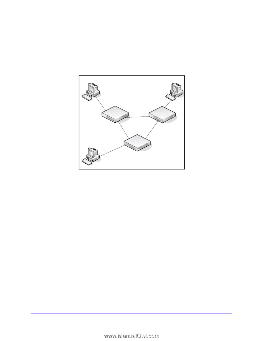
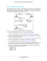
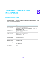
GS716Tv3, GS724Tv4, and GS748Tv5 Smart Switches MSTP Configuration Example This example shows how to create an MSTP instance on the switch. The example network has three different switches that serve different locations in the network. In this example, ports g1-g5 are connected to host stations, so those links are not subject to network loops. Ports g6-g8 are connected across switches 1, 2, and 3. Ports g1-g5 Connected to Hosts Ports g1-g5 Connected to Hosts Ports g6-g8 Connected to Switch 2 and 3 Switch 1 Root Bridge Switch 2 Ports g6-g8 Connected to Switch 1 and 2 Ports g1-g5 Connected to Hosts Switch 3 Perform the following procedures on each switch to configure MSTP: 1. Use the VLAN Configuration screen to create VLANs 300 and 500. For more information about this step, see, Basic VLAN Configuration on page 88. 2. Use the VLAN Membership screen to include ports g1-g8 as tagged (T) or untagged (U) members of VLAN 300 and VLAN 500. For more information about this step, see VLAN Membership Configuration on page 89. 3. From the STP Configuration screen, enable the Spanning Tree State option. For more information about this step, see STP Configuration on page 99. Use the default values for the rest of the STP configuration settings. By default, the STP Operation Mode is MSTP and the Configuration Name is the switch MAC address. 4. From the CST Configuration screen, set the Bridge Priority value for each of the three switches to force Switch 1 to be the root bridge: • Switch 1. 4096 • Switch 2. 12288 • Switch 3. 20480 Configuration Examples 278
-
 1
1 -
2
-
3
-
4
-
5
-
6
-
7
-
8
-
9
-
10
-
11
-
12
-
13
-
14
-
15
-
16
-
17
-
18
-
19
-
20
-
21
-
22
-
23
-
24
-
25
-
26
-
27
-
28
-
29
-
30
-
31
-
32
-
33
-
34
-
35
-
36
-
37
-
38
-
39
-
40
-
41
-
42
-
43
-
44
-
45
-
46
-
47
-
48
-
49
-
50
-
51
-
52
-
53
-
54
-
55
-
56
-
57
-
58
-
59
-
60
-
61
-
62
-
63
-
64
-
65
-
66
-
67
-
68
-
69
-
70
-
71
-
72
-
73
-
74
-
75
-
76
-
77
-
78
-
79
-
80
-
81
-
82
-
83
-
84
-
85
-
86
-
87
-
88
-
89
-
90
-
91
-
92
-
93
-
94
-
95
-
96
-
97
-
98
-
99
-
100
-
101
-
102
-
103
-
104
-
105
-
106
-
107
-
108
-
109
-
110
-
111
-
112
-
113
-
114
-
115
-
116
-
117
-
118
-
119
-
120
-
121
-
122
-
123
-
124
-
125
-
126
-
127
-
128
-
129
-
130
-
131
-
132
-
133
-
134
-
135
-
136
-
137
-
138
-
139
-
140
-
141
-
142
-
143
-
144
-
145
-
146
-
147
-
148
-
149
-
150
-
151
-
152
-
153
-
154
-
155
-
156
-
157
-
158
-
159
-
160
-
161
-
162
-
163
-
164
-
165
-
166
-
167
-
168
-
169
-
170
-
171
-
172
-
173
-
174
-
175
-
176
-
177
-
178
-
179
-
180
-
181
-
182
-
183
-
184
-
185
-
186
-
187
-
188
-
189
-
190
-
191
-
192
-
193
-
194
-
195
-
196
-
197
-
198
-
199
-
200
-
201
-
202
-
203
-
204
-
205
-
206
-
207
-
208
-
209
-
210
-
211
-
212
-
213
-
214
-
215
-
216
-
217
-
218
-
219
-
220
-
221
-
222
-
223
-
224
-
225
-
226
-
227
-
228
-
229
-
230
-
231
-
232
-
233
-
234
-
235
-
236
-
237
-
238
-
239
-
240
-
241
-
242
-
243
-
244
-
245
-
246
-
247
-
248
-
249
-
250
-
251
-
252
-
253
-
254
-
255
-
256
-
257
-
258
-
259
-
260
-
261
-
262
-
263
-
264
-
265
-
266
-
267
-
268
-
269
-
270
-
271
-
272
-
 273
273 -
 274
274 -
 275
275 -
 276
276 -
 277
277 -
 278
278 -
 279
279 -
 280
280 -
 281
281 -
 282
282 -
 283
283 -
284
-
285
-
286
-
287
-
288
-
289
-
290
 |
 |