Netgear GS748Tv5 Software Administration Manual - Page 231
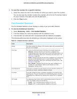
Port Detailed Statistics, To reset the counters for a specific interface, Clear
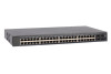 |
View all Netgear GS748Tv5 manuals
Add to My Manuals
Save this manual to your list of manuals |
Page 231 highlights
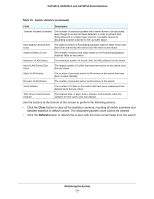
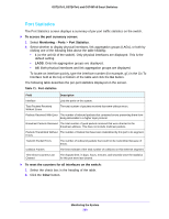
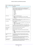
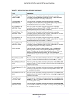
GS716Tv3, GS724Tv4, and GS748Tv5 Smart Switches To reset the counters for a specific interface: 1. Select the check box next to the interface for which you want to clear the counters. You can also type the interface number (for example, g7) in the Go To Interface field at the top or bottom of the table and click the Go button. 2. Click the Clear button. Port Detailed Statistics The Port Detailed Statistics screen displays a variety of per-port traffic statistics. To view the detailed port statistics: 1. Select Monitoring > Ports > Port Detailed Statistics. 2. From the Interface list, select the interface with the statistics to view. 3. From the MST list, select the MST ID associated with the interface (if available). The following table describes the detailed port information displayed on the screen. Table 72. Detailed interface statistics Field ifIndex Port Type Port Channel ID Port Role STP Mode Description This field indicates the ifIndex of the interface table entry associated with this port on an adapter. For most ports this field is blank. Otherwise the possible values are: • Mirrored. Indicates that the port has been configured as a monitoring port and is the source port in a port mirroring session. For additional information about port monitoring and probe ports, see Mirroring on page 245. • Probe. Indicates that the port has been configured as a monitoring port and is the destination port in a port mirroring session. For additional information about port monitoring and probe ports, see Mirroring on page 245. • Port Channel. Indicates that the port has been configured as a member of a port-channel, which is also known as a Link Aggregation Group (LAG). If the port is a member of a port channel, the port channel's interface ID and name are shown. Otherwise, Disable is shown. Each MST Bridge Port that is enabled is assigned a Port Role for each spanning tree. The port role will be one of the following values: Root Port, Designated Port, Alternate Port, Backup Port, Master Port, or Disabled Port. The Spanning Tree Protocol (STP) Administrative Mode for the port or LAG. The possible values for this field are: • Enable. STP is administratively enabled on this port. • Disable. STP is administratively disabled on this port. Monitoring the System 231
-
 1
1 -
2
-
3
-
4
-
5
-
6
-
7
-
8
-
9
-
10
-
11
-
12
-
13
-
14
-
15
-
16
-
17
-
18
-
19
-
20
-
21
-
22
-
23
-
24
-
25
-
26
-
27
-
28
-
29
-
30
-
31
-
32
-
33
-
34
-
35
-
36
-
37
-
38
-
39
-
40
-
41
-
42
-
43
-
44
-
45
-
46
-
47
-
48
-
49
-
50
-
51
-
52
-
53
-
54
-
55
-
56
-
57
-
58
-
59
-
60
-
61
-
62
-
63
-
64
-
65
-
66
-
67
-
68
-
69
-
70
-
71
-
72
-
73
-
74
-
75
-
76
-
77
-
78
-
79
-
80
-
81
-
82
-
83
-
84
-
85
-
86
-
87
-
88
-
89
-
90
-
91
-
92
-
93
-
94
-
95
-
96
-
97
-
98
-
99
-
100
-
101
-
102
-
103
-
104
-
105
-
106
-
107
-
108
-
109
-
110
-
111
-
112
-
113
-
114
-
115
-
116
-
117
-
118
-
119
-
120
-
121
-
122
-
123
-
124
-
125
-
126
-
127
-
128
-
129
-
130
-
131
-
132
-
133
-
134
-
135
-
136
-
137
-
138
-
139
-
140
-
141
-
142
-
143
-
144
-
145
-
146
-
147
-
148
-
149
-
150
-
151
-
152
-
153
-
154
-
155
-
156
-
157
-
158
-
159
-
160
-
161
-
162
-
163
-
164
-
165
-
166
-
167
-
168
-
169
-
170
-
171
-
172
-
173
-
174
-
175
-
176
-
177
-
178
-
179
-
180
-
181
-
182
-
183
-
184
-
185
-
186
-
187
-
188
-
189
-
190
-
191
-
192
-
193
-
194
-
195
-
196
-
197
-
198
-
199
-
200
-
201
-
202
-
203
-
204
-
205
-
206
-
207
-
208
-
209
-
210
-
211
-
212
-
213
-
214
-
215
-
216
-
217
-
218
-
219
-
220
-
221
-
222
-
223
-
224
-
225
-
 226
226 -
 227
227 -
 228
228 -
 229
229 -
 230
230 -
 231
231 -
 232
232 -
 233
233 -
 234
234 -
 235
235 -
 236
236 -
237
-
238
-
239
-
240
-
241
-
242
-
243
-
244
-
245
-
246
-
247
-
248
-
249
-
250
-
251
-
252
-
253
-
254
-
255
-
256
-
257
-
258
-
259
-
260
-
261
-
262
-
263
-
264
-
265
-
266
-
267
-
268
-
269
-
270
-
271
-
272
-
273
-
274
-
275
-
276
-
277
-
278
-
279
-
280
-
281
-
282
-
283
-
284
-
285
-
286
-
287
-
288
-
289
-
290
 |
 |