Cisco 3825 Hardware Installation Guide - Page 157
Installing PVDM2 Modules,
 |
UPC - 746320981505
View all Cisco 3825 manuals
Add to My Manuals
Save this manual to your list of manuals |
Page 157 highlights
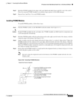
Chapter 8 Connecting Voice Network Modules IP Communications High-Density Digital Voice or Fax Network Module Step 3 Step 4 Hold the PVDM2 module by the edges with your thumb and index finger and lift it out of the socket. Place the removed PVDM2 module in an antistatic bag to protect it from ESD damage. Repeat Step 2 and Step 3 for each PVDM2 module. Installing PVDM2 Modules To install PVDM2 modules, follow these steps: Step 1 Find the PVDM2 sockets on the NM-HDV2 network module. (See Figure 8-17.) Caution Handle PVDM2 modules by the card edges only. PVDM2 modules are ESD-sensitive components and can be damaged by mishandling. Step 2 Step 3 Step 4 Hold the PVDM2 module with the polarization notch on the right, near the back of the chassis, with the connector edge at the bottom. (See Figure 8-18.) Again, to make your job easier, begin with socket 0, then socket 1, or socket 2, then socket 3. Insert the PVDM2 module into the connector slot at an angle, tilted toward the left side of the chassis. Align the PVDM2 module in a vertical position (see Figure 8-20), by using the minimum amount of force required. When the PVDM2 module is properly seated, the socket guide posts fit through the alignment holes, and the connector springs click into place. Ensure that each PVDM2 module is straight and that the alignment holes (as shown in Figure 8-19) line up with the plastic guides on the socket. Note Be sure to align the alignment notch in the bottom of the PVDM2 module with the rib in the 80-pin socket. Figure 8-20 Installing PVDM2 Modules View from front of board 1. Insert the PVDM2 into the socket at an angle from vertical. 2. Push the top of the PVDM2 down and back. 3. The socket guide posts fit through the holes in the PVDM2. 4. The locking springs clip the back of the PVDM2. 103280 OL-2485-20 Cisco Network Modules Hardware Installation Guide 8-15
-
 1
1 -
2
-
3
-
4
-
5
-
6
-
7
-
8
-
9
-
10
-
11
-
12
-
13
-
14
-
15
-
16
-
17
-
18
-
19
-
20
-
21
-
22
-
23
-
24
-
25
-
26
-
27
-
28
-
29
-
30
-
31
-
32
-
33
-
34
-
35
-
36
-
37
-
38
-
39
-
40
-
41
-
42
-
43
-
44
-
45
-
46
-
47
-
48
-
49
-
50
-
51
-
52
-
53
-
54
-
55
-
56
-
57
-
58
-
59
-
60
-
61
-
62
-
63
-
64
-
65
-
66
-
67
-
68
-
69
-
70
-
71
-
72
-
73
-
74
-
75
-
76
-
77
-
78
-
79
-
80
-
81
-
82
-
83
-
84
-
85
-
86
-
87
-
88
-
89
-
90
-
91
-
92
-
93
-
94
-
95
-
96
-
97
-
98
-
99
-
100
-
101
-
102
-
103
-
104
-
105
-
106
-
107
-
108
-
109
-
110
-
111
-
112
-
113
-
114
-
115
-
116
-
117
-
118
-
119
-
120
-
121
-
122
-
123
-
124
-
125
-
126
-
127
-
128
-
129
-
130
-
131
-
132
-
133
-
134
-
135
-
136
-
137
-
138
-
139
-
140
-
141
-
142
-
143
-
144
-
145
-
146
-
147
-
148
-
149
-
150
-
151
-
 152
152 -
 153
153 -
 154
154 -
 155
155 -
 156
156 -
 157
157 -
 158
158 -
 159
159 -
 160
160 -
 161
161 -
 162
162 -
163
-
164
-
165
-
166
-
167
-
168
-
169
-
170
-
171
-
172
-
173
-
174
-
175
-
176
-
177
-
178
-
179
-
180
-
181
-
182
-
183
-
184
-
185
-
186
-
187
-
188
-
189
-
190
-
191
-
192
-
193
-
194
-
195
-
196
-
197
-
198
-
199
-
200
-
201
-
202
-
203
-
204
-
205
-
206
-
207
-
208
-
209
-
210
-
211
-
212
-
213
-
214
-
215
-
216
-
217
-
218
-
219
-
220
-
221
-
222
-
223
-
224
-
225
-
226
-
227
-
228
-
229
-
230
-
231
-
232
-
233
-
234
-
235
-
236
-
237
-
238
-
239
-
240
-
241
-
242
-
243
-
244
-
245
-
246
-
247
-
248
-
249
-
250
-
251
-
252
-
253
-
254
-
255
-
256
-
257
-
258
-
259
-
260
-
261
-
262
-
263
-
264
-
265
-
266
-
267
-
268
-
269
-
270
-
271
-
272
-
273
-
274
-
275
-
276
-
277
-
278
-
279
-
280
-
281
-
282
-
283
-
284
-
285
-
286
-
287
-
288
-
289
-
290
-
291
-
292
-
293
-
294
-
295
-
296
-
297
-
298
-
299
-
300
-
301
-
302
-
303
-
304
-
305
-
306
-
307
-
308
-
309
-
310
-
311
-
312
-
313
-
314
-
315
-
316
-
317
-
318
-
319
-
320
-
321
-
322
-
323
-
324
-
325
-
326
-
327
-
328
-
329
-
330
-
331
-
332
-
333
-
334
-
335
-
336
-
337
-
338
-
339
-
340
-
341
-
342
-
343
-
344
-
345
-
346
-
347
-
348
-
349
-
350
-
351
-
352
-
353
-
354
-
355
-
356
-
357
-
358
-
359
-
360
-
361
-
362
-
363
-
364
-
365
-
366
-
367
-
368
-
369
-
370
-
371
-
372
-
373
-
374
-
375
-
376
-
377
-
378
-
379
-
380
-
381
-
382
-
383
-
384
-
385
-
386
-
387
-
388
-
389
-
390
-
391
-
392
-
393
-
394
-
395
-
396
-
397
-
398
-
399
-
400
-
401
-
402
-
403
-
404
-
405
-
406
-
407
-
408
-
409
-
410
-
411
-
412
-
413
-
414
-
415
-
416
-
417
-
418
 |
 |
