Cisco 3825 Hardware Installation Guide - Page 79
Ethernet Connectors, Connecting Ethernet Ports, AUI Connections
 |
UPC - 746320981505
View all Cisco 3825 manuals
Add to My Manuals
Save this manual to your list of manuals |
Page 79 highlights
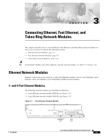
Chapter 3 Connecting Ethernet, Fast Ethernet, and Token Ring Network Modules Ethernet Network Modules 16MBPS IN-RING ACT LNK H6555 Figure 3-5 1-Ethernet 1-Token Ring 2-WAN Card Slot Network Module 1E 1R W1 Token Ring interface LEDs 10BASE-T WO port AUI port STP AUI EN TOKEN RING 0 ETHERNET 0 STP port UTP port Ethernet LEDs Ethernet Connectors The 1-port Ethernet network module, the 1-Ethernet 2-slot network module, and the 1-Ethernet 1-Token Ring 2-slot network module each provide a single Ethernet port. This port uses either the attachment unit interface (AUI) DB-15 connector on the right side of the module or the 10BASE-T (RJ-45) connector next to it. Only one of these connectors can be active at a time. The active port is identified in software by port type (Ethernet), slot number on the module, and port number 0. All modules detect the type of network connection automatically, and you do not need to choose the media type in software. If cables are plugged into both ports, the 10BASE-T connection is chosen. The 4-port Ethernet network module has ports for four Ethernet connections (0, 1, 2, and 3). Port 0 offers a choice of an AUI or 10BASE-T interface. Ethernet ports 1, 2, and 3 use 10BASE-T connectors only. These ports do not provide an AUI connector. The 2-Ethernet 2-slot network module has ports for two Ethernet connections. Port 0 offers a choice of AUI or 10BASE-T. Port 1 uses 10BASE-T only. Connecting Ethernet Ports If an Ethernet port offers both an AUI connector and a 10BASE-T connector, you can use either connector, but not both at the same time. AUI Connections Use an Ethernet AUI cable to connect an AUI port to an Ethernet transceiver. These ports are color-coded yellow. The female end of the AUI cable mates with the slide-latch connector of the transceiver cable. Figure 3-6 shows a thin Ethernet transceiver as an example, but you can use any type of Ethernet transceiver. If the transceiver cable has thumbscrew connectors, you can connect it directly to the AUI port by replacing the AUI port slide latch with a jackscrew (provided in a separate bag). OL-2485-20 Cisco Network Modules Hardware Installation Guide 3-3
-
 1
1 -
2
-
3
-
4
-
5
-
6
-
7
-
8
-
9
-
10
-
11
-
12
-
13
-
14
-
15
-
16
-
17
-
18
-
19
-
20
-
21
-
22
-
23
-
24
-
25
-
26
-
27
-
28
-
29
-
30
-
31
-
32
-
33
-
34
-
35
-
36
-
37
-
38
-
39
-
40
-
41
-
42
-
43
-
44
-
45
-
46
-
47
-
48
-
49
-
50
-
51
-
52
-
53
-
54
-
55
-
56
-
57
-
58
-
59
-
60
-
61
-
62
-
63
-
64
-
65
-
66
-
67
-
68
-
69
-
70
-
71
-
72
-
73
-
 74
74 -
 75
75 -
 76
76 -
 77
77 -
 78
78 -
 79
79 -
 80
80 -
 81
81 -
 82
82 -
 83
83 -
 84
84 -
85
-
86
-
87
-
88
-
89
-
90
-
91
-
92
-
93
-
94
-
95
-
96
-
97
-
98
-
99
-
100
-
101
-
102
-
103
-
104
-
105
-
106
-
107
-
108
-
109
-
110
-
111
-
112
-
113
-
114
-
115
-
116
-
117
-
118
-
119
-
120
-
121
-
122
-
123
-
124
-
125
-
126
-
127
-
128
-
129
-
130
-
131
-
132
-
133
-
134
-
135
-
136
-
137
-
138
-
139
-
140
-
141
-
142
-
143
-
144
-
145
-
146
-
147
-
148
-
149
-
150
-
151
-
152
-
153
-
154
-
155
-
156
-
157
-
158
-
159
-
160
-
161
-
162
-
163
-
164
-
165
-
166
-
167
-
168
-
169
-
170
-
171
-
172
-
173
-
174
-
175
-
176
-
177
-
178
-
179
-
180
-
181
-
182
-
183
-
184
-
185
-
186
-
187
-
188
-
189
-
190
-
191
-
192
-
193
-
194
-
195
-
196
-
197
-
198
-
199
-
200
-
201
-
202
-
203
-
204
-
205
-
206
-
207
-
208
-
209
-
210
-
211
-
212
-
213
-
214
-
215
-
216
-
217
-
218
-
219
-
220
-
221
-
222
-
223
-
224
-
225
-
226
-
227
-
228
-
229
-
230
-
231
-
232
-
233
-
234
-
235
-
236
-
237
-
238
-
239
-
240
-
241
-
242
-
243
-
244
-
245
-
246
-
247
-
248
-
249
-
250
-
251
-
252
-
253
-
254
-
255
-
256
-
257
-
258
-
259
-
260
-
261
-
262
-
263
-
264
-
265
-
266
-
267
-
268
-
269
-
270
-
271
-
272
-
273
-
274
-
275
-
276
-
277
-
278
-
279
-
280
-
281
-
282
-
283
-
284
-
285
-
286
-
287
-
288
-
289
-
290
-
291
-
292
-
293
-
294
-
295
-
296
-
297
-
298
-
299
-
300
-
301
-
302
-
303
-
304
-
305
-
306
-
307
-
308
-
309
-
310
-
311
-
312
-
313
-
314
-
315
-
316
-
317
-
318
-
319
-
320
-
321
-
322
-
323
-
324
-
325
-
326
-
327
-
328
-
329
-
330
-
331
-
332
-
333
-
334
-
335
-
336
-
337
-
338
-
339
-
340
-
341
-
342
-
343
-
344
-
345
-
346
-
347
-
348
-
349
-
350
-
351
-
352
-
353
-
354
-
355
-
356
-
357
-
358
-
359
-
360
-
361
-
362
-
363
-
364
-
365
-
366
-
367
-
368
-
369
-
370
-
371
-
372
-
373
-
374
-
375
-
376
-
377
-
378
-
379
-
380
-
381
-
382
-
383
-
384
-
385
-
386
-
387
-
388
-
389
-
390
-
391
-
392
-
393
-
394
-
395
-
396
-
397
-
398
-
399
-
400
-
401
-
402
-
403
-
404
-
405
-
406
-
407
-
408
-
409
-
410
-
411
-
412
-
413
-
414
-
415
-
416
-
417
-
418
 |
 |
