Cisco 3825 Hardware Installation Guide - Page 223
Adding an Optional Power Board
 |
UPC - 746320981505
View all Cisco 3825 manuals
Add to My Manuals
Save this manual to your list of manuals |
Page 223 highlights
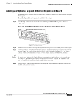
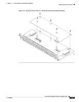
Chapter 17 Connecting Ethernet Switch Network Modules Adding an Optional Power Board Adding an Optional Power Board An optional power board can be used if the Ethernet switch network module requires external -48-V power for IP telephones. Installation and configuration of the external power supply system is described in the Cisco External Power Supply for Cisco Ethernet Switch Network Modules Installation Guide. To install power boards, follow these steps: Step 1 Use a Phillips screwdriver to remove the cover on the external power board port, as shown in Figure 17-7. Figure 17-7 Power Board Port Cover on the Ethernet Switch Network Module NM- ESW16 15x External power supply port cover FastEthernet Ports 8x 7x 15x 7x 14x 6x 13x 5x 12x 4x 11x 3x 10x 2x 9x 1x 0x 8x 0x Ext Pwr -48V GE 1100/01000/ Base-Tx EN 62426 Step 2 Step 3 Step 4 Gigabit Ethernet port cover On the power board, remove the thumb screws on either side of the power board port. Put these in a safe place, because they will be replaced when the power board is installed. Guide the external connector through the power board port opening on the card faceplate. Insert the connector on the power board into the connector on the network module. (See Figure 17-8 for 16-port Ethernet switch network modules and Figure 17-9 for 36-port Ethernet switch network modules.) Note Be sure to press firmly on the power board until the board seats correctly onto the connector. Step 5 Step 6 Insert the screws from the board installation kit through the power board into the standoffs on the network module. Replace the thumbscrews on either side of the power board port. Make sure that the thumbscrews are tightened firmly. Warning Do not connect the external power supply cable to the power connector on the front of the network module until the network module has been inserted into the router chassis. Step 7 After installing the network module into the chassis, connect the power cable to the power module connector on the front of the network module. See the Cisco External Power Supply for Cisco Ethernet Switch Network Modules Installation Guide for more information. OL-2485-20 Cisco Network Modules Hardware Installation Guide 17-7
-
 1
1 -
2
-
3
-
4
-
5
-
6
-
7
-
8
-
9
-
10
-
11
-
12
-
13
-
14
-
15
-
16
-
17
-
18
-
19
-
20
-
21
-
22
-
23
-
24
-
25
-
26
-
27
-
28
-
29
-
30
-
31
-
32
-
33
-
34
-
35
-
36
-
37
-
38
-
39
-
40
-
41
-
42
-
43
-
44
-
45
-
46
-
47
-
48
-
49
-
50
-
51
-
52
-
53
-
54
-
55
-
56
-
57
-
58
-
59
-
60
-
61
-
62
-
63
-
64
-
65
-
66
-
67
-
68
-
69
-
70
-
71
-
72
-
73
-
74
-
75
-
76
-
77
-
78
-
79
-
80
-
81
-
82
-
83
-
84
-
85
-
86
-
87
-
88
-
89
-
90
-
91
-
92
-
93
-
94
-
95
-
96
-
97
-
98
-
99
-
100
-
101
-
102
-
103
-
104
-
105
-
106
-
107
-
108
-
109
-
110
-
111
-
112
-
113
-
114
-
115
-
116
-
117
-
118
-
119
-
120
-
121
-
122
-
123
-
124
-
125
-
126
-
127
-
128
-
129
-
130
-
131
-
132
-
133
-
134
-
135
-
136
-
137
-
138
-
139
-
140
-
141
-
142
-
143
-
144
-
145
-
146
-
147
-
148
-
149
-
150
-
151
-
152
-
153
-
154
-
155
-
156
-
157
-
158
-
159
-
160
-
161
-
162
-
163
-
164
-
165
-
166
-
167
-
168
-
169
-
170
-
171
-
172
-
173
-
174
-
175
-
176
-
177
-
178
-
179
-
180
-
181
-
182
-
183
-
184
-
185
-
186
-
187
-
188
-
189
-
190
-
191
-
192
-
193
-
194
-
195
-
196
-
197
-
198
-
199
-
200
-
201
-
202
-
203
-
204
-
205
-
206
-
207
-
208
-
209
-
210
-
211
-
212
-
213
-
214
-
215
-
216
-
217
-
 218
218 -
 219
219 -
 220
220 -
 221
221 -
 222
222 -
 223
223 -
 224
224 -
 225
225 -
 226
226 -
 227
227 -
 228
228 -
229
-
230
-
231
-
232
-
233
-
234
-
235
-
236
-
237
-
238
-
239
-
240
-
241
-
242
-
243
-
244
-
245
-
246
-
247
-
248
-
249
-
250
-
251
-
252
-
253
-
254
-
255
-
256
-
257
-
258
-
259
-
260
-
261
-
262
-
263
-
264
-
265
-
266
-
267
-
268
-
269
-
270
-
271
-
272
-
273
-
274
-
275
-
276
-
277
-
278
-
279
-
280
-
281
-
282
-
283
-
284
-
285
-
286
-
287
-
288
-
289
-
290
-
291
-
292
-
293
-
294
-
295
-
296
-
297
-
298
-
299
-
300
-
301
-
302
-
303
-
304
-
305
-
306
-
307
-
308
-
309
-
310
-
311
-
312
-
313
-
314
-
315
-
316
-
317
-
318
-
319
-
320
-
321
-
322
-
323
-
324
-
325
-
326
-
327
-
328
-
329
-
330
-
331
-
332
-
333
-
334
-
335
-
336
-
337
-
338
-
339
-
340
-
341
-
342
-
343
-
344
-
345
-
346
-
347
-
348
-
349
-
350
-
351
-
352
-
353
-
354
-
355
-
356
-
357
-
358
-
359
-
360
-
361
-
362
-
363
-
364
-
365
-
366
-
367
-
368
-
369
-
370
-
371
-
372
-
373
-
374
-
375
-
376
-
377
-
378
-
379
-
380
-
381
-
382
-
383
-
384
-
385
-
386
-
387
-
388
-
389
-
390
-
391
-
392
-
393
-
394
-
395
-
396
-
397
-
398
-
399
-
400
-
401
-
402
-
403
-
404
-
405
-
406
-
407
-
408
-
409
-
410
-
411
-
412
-
413
-
414
-
415
-
416
-
417
-
418
 |
 |
