Cisco 3825 Hardware Installation Guide - Page 354
How to Install, Connect, or Replace the NM-1VSAT-GILAT Network Module
 |
UPC - 746320981505
View all Cisco 3825 manuals
Add to My Manuals
Save this manual to your list of manuals |
Page 354 highlights
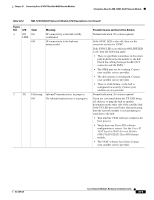
Chapter 33 Connecting Cisco IP VSAT Satellite WAN Network Modules How to Install, Connect, or Replace the NM-1VSAT-GILAT Network Module Table 33-2 NM-1VSAT-GILAT Network Module LED Descriptions (continued) Figure Ref. LED State Meaning Possible Causes and Corrective Actions 6 EN On The router's Cisco IOS software recognizes the network module. Normal indication. No action required. Off The router's Cisco IOS software does not Verify that the network module is properly recognize the network module. installed in the router chassis. See the "Installing Cisco Network Modules in Cisco Access Routers" chapter. 1. ODU = outdoor unit. 2. VSAT = very small aperture terminal. 3. DVB = Digital Video Broadcasting. 4. The receive direction at the remote VSAT is called the outbound direction from the hub. See the "Outbound and Inbound Directions in a Satellite Communications Network" section on page 33-7. 5. LNB = low noise block converter. 6. RF = radio frequency. 7. SSPA = solid state block converter and power amplifier. 8. The transmit direction at the remote VSAT is called the inbound direction to the hub. See the "Outbound and Inbound Directions in a Satellite Communications Network" section on page 33-7. How to Install, Connect, or Replace the NM-1VSAT-GILAT Network Module This section contains the following procedures, each of which may or may not be required, depending on which tasks your satellite service provider performs for you: • Installing the NM-1VSAT-GILAT Network Module in the Router Chassis, page 33-10 • Connecting the NM-1VSAT-GILAT Network Module to the ODU, page 33-10 • Connecting the NM-1VSAT-GILAT Network Module to the External Power Supply, page 33-12 • Replacing the NM-1VSAT-GILAT Network Module in the Router Chassis, page 33-14 Installing the NM-1VSAT-GILAT Network Module in the Router Chassis To install the NM-1VSAT-GILAT network module in the router chassis, see the "Installing Cisco Network Modules in Cisco Access Routers" chapter of the Cisco Network Modules Hardware Installation Guide. Connecting the NM-1VSAT-GILAT Network Module to the ODU This section describes how to connect the NM-1VSAT-GILAT network module to the ODU. Shielded RG-6, RG-11, or both types of RF cables are used to connect the NM-1VSAT-GILAT network module to the ODU. Typically, a satellite service provider installation technician installs the ODU, connects RG-11 cables to the dish antenna, and runs the RG-11 cables to the area near the router. The technician also typically terminates the RG-11 cables and adds short RG-6 cables, which are then connected to the NM-1VSAT-GILAT network module in the router. 33-10 Cisco Network Modules Hardware Installation Guide OL-2485-20
-
 1
1 -
2
-
3
-
4
-
5
-
6
-
7
-
8
-
9
-
10
-
11
-
12
-
13
-
14
-
15
-
16
-
17
-
18
-
19
-
20
-
21
-
22
-
23
-
24
-
25
-
26
-
27
-
28
-
29
-
30
-
31
-
32
-
33
-
34
-
35
-
36
-
37
-
38
-
39
-
40
-
41
-
42
-
43
-
44
-
45
-
46
-
47
-
48
-
49
-
50
-
51
-
52
-
53
-
54
-
55
-
56
-
57
-
58
-
59
-
60
-
61
-
62
-
63
-
64
-
65
-
66
-
67
-
68
-
69
-
70
-
71
-
72
-
73
-
74
-
75
-
76
-
77
-
78
-
79
-
80
-
81
-
82
-
83
-
84
-
85
-
86
-
87
-
88
-
89
-
90
-
91
-
92
-
93
-
94
-
95
-
96
-
97
-
98
-
99
-
100
-
101
-
102
-
103
-
104
-
105
-
106
-
107
-
108
-
109
-
110
-
111
-
112
-
113
-
114
-
115
-
116
-
117
-
118
-
119
-
120
-
121
-
122
-
123
-
124
-
125
-
126
-
127
-
128
-
129
-
130
-
131
-
132
-
133
-
134
-
135
-
136
-
137
-
138
-
139
-
140
-
141
-
142
-
143
-
144
-
145
-
146
-
147
-
148
-
149
-
150
-
151
-
152
-
153
-
154
-
155
-
156
-
157
-
158
-
159
-
160
-
161
-
162
-
163
-
164
-
165
-
166
-
167
-
168
-
169
-
170
-
171
-
172
-
173
-
174
-
175
-
176
-
177
-
178
-
179
-
180
-
181
-
182
-
183
-
184
-
185
-
186
-
187
-
188
-
189
-
190
-
191
-
192
-
193
-
194
-
195
-
196
-
197
-
198
-
199
-
200
-
201
-
202
-
203
-
204
-
205
-
206
-
207
-
208
-
209
-
210
-
211
-
212
-
213
-
214
-
215
-
216
-
217
-
218
-
219
-
220
-
221
-
222
-
223
-
224
-
225
-
226
-
227
-
228
-
229
-
230
-
231
-
232
-
233
-
234
-
235
-
236
-
237
-
238
-
239
-
240
-
241
-
242
-
243
-
244
-
245
-
246
-
247
-
248
-
249
-
250
-
251
-
252
-
253
-
254
-
255
-
256
-
257
-
258
-
259
-
260
-
261
-
262
-
263
-
264
-
265
-
266
-
267
-
268
-
269
-
270
-
271
-
272
-
273
-
274
-
275
-
276
-
277
-
278
-
279
-
280
-
281
-
282
-
283
-
284
-
285
-
286
-
287
-
288
-
289
-
290
-
291
-
292
-
293
-
294
-
295
-
296
-
297
-
298
-
299
-
300
-
301
-
302
-
303
-
304
-
305
-
306
-
307
-
308
-
309
-
310
-
311
-
312
-
313
-
314
-
315
-
316
-
317
-
318
-
319
-
320
-
321
-
322
-
323
-
324
-
325
-
326
-
327
-
328
-
329
-
330
-
331
-
332
-
333
-
334
-
335
-
336
-
337
-
338
-
339
-
340
-
341
-
342
-
343
-
344
-
345
-
346
-
347
-
348
-
 349
349 -
 350
350 -
 351
351 -
 352
352 -
 353
353 -
 354
354 -
 355
355 -
 356
356 -
 357
357 -
 358
358 -
 359
359 -
360
-
361
-
362
-
363
-
364
-
365
-
366
-
367
-
368
-
369
-
370
-
371
-
372
-
373
-
374
-
375
-
376
-
377
-
378
-
379
-
380
-
381
-
382
-
383
-
384
-
385
-
386
-
387
-
388
-
389
-
390
-
391
-
392
-
393
-
394
-
395
-
396
-
397
-
398
-
399
-
400
-
401
-
402
-
403
-
404
-
405
-
406
-
407
-
408
-
409
-
410
-
411
-
412
-
413
-
414
-
415
-
416
-
417
-
418
 |
 |
