Cisco 3825 Hardware Installation Guide - Page 190
Fiber-Optic Transmission Specifications, SONET Distance Limitations - bundle
 |
UPC - 746320981505
View all Cisco 3825 manuals
Add to My Manuals
Save this manual to your list of manuals |
Page 190 highlights
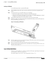
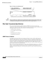
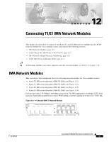
ATM OC-3 Network Modules Chapter 11 Connecting ATM Network Modules Figure 11-19 Class 1 Laser Warning Label CLASS 1 LASER PRODUCT LASERPRODUKT DER KLASSE 1 PRODUIT LASER DE CLASSE 1 PRODUCTO LASER CLASE 1 ATM 1A-OC3MM CLASS 1 LASER PRODUCT LASERPRODUCT DER KLASSE 1 PRODUCT LASER DE CLASSE1 PRODUCTO LASER CLASE 1 RCLK FERF OOF AIS ATM 0 EN 14862 Warning Because invisible laser radiation may be emitted from the aperture of the port when no fiber cable is connected, avoid exposure to laser radiation and do not stare into open apertures. Statement 240 Fiber-Optic Transmission Specifications This section describes Synchronous Optical Network (SONET) specifications for fiber-optic transmissions, defines the power budget, and helps you estimate your power margin for multimode and single-mode transmissions. This section contains the following information: • SONET Distance Limitations • Power Budget and Power Margin • Link Loss • Estimating the Power Margin • Single-Mode Transmission SONET Distance Limitations The SONET specification for fiber-optic transmission defines two types of fiber, single-mode and multimode. Single-mode fiber allows only one bundle of light rays to propagate through the fiber, whereas multimode fiber allows multiple bundles entering at different angles. Because different bundles (referred to as modes) travel different distances, depending on the entry angle, they arrive at the destination at different times (modal dispersion). Single-mode fiber is capable of higher bandwidth and greater cable run distances than multimode fiber. Table 11-8 lists typical maximum distances for single-mode and multimode transmissions, as defined by SONET. Use the calculations described in this section to determine the actual maximum for your network. If the distance between two connected stations exceeds this limit, transmission can become unreliable. 11-14 Cisco Network Modules Hardware Installation Guide OL-2485-20
-
 1
1 -
2
-
3
-
4
-
5
-
6
-
7
-
8
-
9
-
10
-
11
-
12
-
13
-
14
-
15
-
16
-
17
-
18
-
19
-
20
-
21
-
22
-
23
-
24
-
25
-
26
-
27
-
28
-
29
-
30
-
31
-
32
-
33
-
34
-
35
-
36
-
37
-
38
-
39
-
40
-
41
-
42
-
43
-
44
-
45
-
46
-
47
-
48
-
49
-
50
-
51
-
52
-
53
-
54
-
55
-
56
-
57
-
58
-
59
-
60
-
61
-
62
-
63
-
64
-
65
-
66
-
67
-
68
-
69
-
70
-
71
-
72
-
73
-
74
-
75
-
76
-
77
-
78
-
79
-
80
-
81
-
82
-
83
-
84
-
85
-
86
-
87
-
88
-
89
-
90
-
91
-
92
-
93
-
94
-
95
-
96
-
97
-
98
-
99
-
100
-
101
-
102
-
103
-
104
-
105
-
106
-
107
-
108
-
109
-
110
-
111
-
112
-
113
-
114
-
115
-
116
-
117
-
118
-
119
-
120
-
121
-
122
-
123
-
124
-
125
-
126
-
127
-
128
-
129
-
130
-
131
-
132
-
133
-
134
-
135
-
136
-
137
-
138
-
139
-
140
-
141
-
142
-
143
-
144
-
145
-
146
-
147
-
148
-
149
-
150
-
151
-
152
-
153
-
154
-
155
-
156
-
157
-
158
-
159
-
160
-
161
-
162
-
163
-
164
-
165
-
166
-
167
-
168
-
169
-
170
-
171
-
172
-
173
-
174
-
175
-
176
-
177
-
178
-
179
-
180
-
181
-
182
-
183
-
184
-
 185
185 -
 186
186 -
 187
187 -
 188
188 -
 189
189 -
 190
190 -
 191
191 -
 192
192 -
 193
193 -
 194
194 -
 195
195 -
196
-
197
-
198
-
199
-
200
-
201
-
202
-
203
-
204
-
205
-
206
-
207
-
208
-
209
-
210
-
211
-
212
-
213
-
214
-
215
-
216
-
217
-
218
-
219
-
220
-
221
-
222
-
223
-
224
-
225
-
226
-
227
-
228
-
229
-
230
-
231
-
232
-
233
-
234
-
235
-
236
-
237
-
238
-
239
-
240
-
241
-
242
-
243
-
244
-
245
-
246
-
247
-
248
-
249
-
250
-
251
-
252
-
253
-
254
-
255
-
256
-
257
-
258
-
259
-
260
-
261
-
262
-
263
-
264
-
265
-
266
-
267
-
268
-
269
-
270
-
271
-
272
-
273
-
274
-
275
-
276
-
277
-
278
-
279
-
280
-
281
-
282
-
283
-
284
-
285
-
286
-
287
-
288
-
289
-
290
-
291
-
292
-
293
-
294
-
295
-
296
-
297
-
298
-
299
-
300
-
301
-
302
-
303
-
304
-
305
-
306
-
307
-
308
-
309
-
310
-
311
-
312
-
313
-
314
-
315
-
316
-
317
-
318
-
319
-
320
-
321
-
322
-
323
-
324
-
325
-
326
-
327
-
328
-
329
-
330
-
331
-
332
-
333
-
334
-
335
-
336
-
337
-
338
-
339
-
340
-
341
-
342
-
343
-
344
-
345
-
346
-
347
-
348
-
349
-
350
-
351
-
352
-
353
-
354
-
355
-
356
-
357
-
358
-
359
-
360
-
361
-
362
-
363
-
364
-
365
-
366
-
367
-
368
-
369
-
370
-
371
-
372
-
373
-
374
-
375
-
376
-
377
-
378
-
379
-
380
-
381
-
382
-
383
-
384
-
385
-
386
-
387
-
388
-
389
-
390
-
391
-
392
-
393
-
394
-
395
-
396
-
397
-
398
-
399
-
400
-
401
-
402
-
403
-
404
-
405
-
406
-
407
-
408
-
409
-
410
-
411
-
412
-
413
-
414
-
415
-
416
-
417
-
418
 |
 |
