Cisco 3825 Hardware Installation Guide - Page 314
Connecting the AIC Network Module to the Network
 |
UPC - 746320981505
View all Cisco 3825 manuals
Add to My Manuals
Save this manual to your list of manuals |
Page 314 highlights
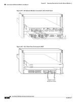
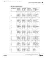
Connecting the AIC Network Module to the Network Chapter 29 Connecting Alarm Interface Controller Network Modules The AIC network module is connected to the network using four high-density SCSI-type connectors on the front panel. Figure 29-1 Alarm Interface Controller Network Module AIC-64 CONN 1 CONN 3 CONN 2 CONN 4 STAT EN 37421 Connecting the AIC Network Module to the Network An AIC network module provides four 50-pin receptacles. Use cables that have male Micro DB-50 connectors at both ends with all conductors straight-wired. Central office equipment is cabled to the patch panel, and then cross-connected to the AIC cable. Two different patch panels can be used. The AIC-1 patch panel terminates one AIC and has voltage terminations with lugs and fuses for voltage monitoring. The AIC-2 patch panel terminates up to two AICs or 128 contact closure points See Figure 29-2 through Figure 29-6 for examples of the AIC connections to the patch panels. See the AIC data sheet on www.cisco.com for recommended patch panel and cable vendors. Caution Damage to the AIC network module can occur if an alarm set for monitoring current is connected to a sensor for monitoring voltage. Make sure that your alarms are connected to the proper sensors. Caution Connect the cable to the AIC before connecting it to the patch panel or other connection. Otherwise, voltage could be present on the male pins that connect to the AIC. Caution The signal I/O connections on this unit are intended only for connection to NEC/CEC Class 2 or equivalent circuit. This means that the voltages applied to I/O connections should not exceed 42.4 Vpk or 60 Vdc and it should be a limited/fused power source. For more details on Class 2 circuits, refer to the National Electrical Code/Canadian Electrical Code. This does not apply to the analog input/output terminal strip numbers 1-8 on the AIC-1 patch panel. Caution This unit is not intended for connection to exposed plant leads. Therefore, it should not be connected to circuit conductors that extend beyond one building and are run so as to be subject to accidental contact with AC main conductors, or are exposed to lightning on interbuilding circuits on the same premises. Ports are numbered from right to left and from bottom to top, as labeled on the module rear panel. Pinouts for the AIC-1 patch panel are shown in Table 29-1. The connector 3 voltage monitor pinouts for AIC-1 are shown in Table 29-2. Pinouts for the AIC-2 patch panel are shown in Table 29-3. 29-2 Cisco Network Modules Hardware Installation Guide OL-2485-20
-
 1
1 -
2
-
3
-
4
-
5
-
6
-
7
-
8
-
9
-
10
-
11
-
12
-
13
-
14
-
15
-
16
-
17
-
18
-
19
-
20
-
21
-
22
-
23
-
24
-
25
-
26
-
27
-
28
-
29
-
30
-
31
-
32
-
33
-
34
-
35
-
36
-
37
-
38
-
39
-
40
-
41
-
42
-
43
-
44
-
45
-
46
-
47
-
48
-
49
-
50
-
51
-
52
-
53
-
54
-
55
-
56
-
57
-
58
-
59
-
60
-
61
-
62
-
63
-
64
-
65
-
66
-
67
-
68
-
69
-
70
-
71
-
72
-
73
-
74
-
75
-
76
-
77
-
78
-
79
-
80
-
81
-
82
-
83
-
84
-
85
-
86
-
87
-
88
-
89
-
90
-
91
-
92
-
93
-
94
-
95
-
96
-
97
-
98
-
99
-
100
-
101
-
102
-
103
-
104
-
105
-
106
-
107
-
108
-
109
-
110
-
111
-
112
-
113
-
114
-
115
-
116
-
117
-
118
-
119
-
120
-
121
-
122
-
123
-
124
-
125
-
126
-
127
-
128
-
129
-
130
-
131
-
132
-
133
-
134
-
135
-
136
-
137
-
138
-
139
-
140
-
141
-
142
-
143
-
144
-
145
-
146
-
147
-
148
-
149
-
150
-
151
-
152
-
153
-
154
-
155
-
156
-
157
-
158
-
159
-
160
-
161
-
162
-
163
-
164
-
165
-
166
-
167
-
168
-
169
-
170
-
171
-
172
-
173
-
174
-
175
-
176
-
177
-
178
-
179
-
180
-
181
-
182
-
183
-
184
-
185
-
186
-
187
-
188
-
189
-
190
-
191
-
192
-
193
-
194
-
195
-
196
-
197
-
198
-
199
-
200
-
201
-
202
-
203
-
204
-
205
-
206
-
207
-
208
-
209
-
210
-
211
-
212
-
213
-
214
-
215
-
216
-
217
-
218
-
219
-
220
-
221
-
222
-
223
-
224
-
225
-
226
-
227
-
228
-
229
-
230
-
231
-
232
-
233
-
234
-
235
-
236
-
237
-
238
-
239
-
240
-
241
-
242
-
243
-
244
-
245
-
246
-
247
-
248
-
249
-
250
-
251
-
252
-
253
-
254
-
255
-
256
-
257
-
258
-
259
-
260
-
261
-
262
-
263
-
264
-
265
-
266
-
267
-
268
-
269
-
270
-
271
-
272
-
273
-
274
-
275
-
276
-
277
-
278
-
279
-
280
-
281
-
282
-
283
-
284
-
285
-
286
-
287
-
288
-
289
-
290
-
291
-
292
-
293
-
294
-
295
-
296
-
297
-
298
-
299
-
300
-
301
-
302
-
303
-
304
-
305
-
306
-
307
-
308
-
 309
309 -
 310
310 -
 311
311 -
 312
312 -
 313
313 -
 314
314 -
 315
315 -
 316
316 -
 317
317 -
 318
318 -
 319
319 -
320
-
321
-
322
-
323
-
324
-
325
-
326
-
327
-
328
-
329
-
330
-
331
-
332
-
333
-
334
-
335
-
336
-
337
-
338
-
339
-
340
-
341
-
342
-
343
-
344
-
345
-
346
-
347
-
348
-
349
-
350
-
351
-
352
-
353
-
354
-
355
-
356
-
357
-
358
-
359
-
360
-
361
-
362
-
363
-
364
-
365
-
366
-
367
-
368
-
369
-
370
-
371
-
372
-
373
-
374
-
375
-
376
-
377
-
378
-
379
-
380
-
381
-
382
-
383
-
384
-
385
-
386
-
387
-
388
-
389
-
390
-
391
-
392
-
393
-
394
-
395
-
396
-
397
-
398
-
399
-
400
-
401
-
402
-
403
-
404
-
405
-
406
-
407
-
408
-
409
-
410
-
411
-
412
-
413
-
414
-
415
-
416
-
417
-
418
 |
 |
