Cisco 3825 Hardware Installation Guide - Page 417
Slide the network module out of the slot
 |
UPC - 746320981505
View all Cisco 3825 manuals
Add to My Manuals
Save this manual to your list of manuals |
Page 417 highlights
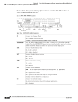
Chapter 40 Cisco Video Management and Storage System Enhanced Network Modules Online Insertion and Removal of Cisco Network Modules Procedure For a description of informational and error messages that may appear on the console during this procedure, see the hardware installation guide for your router. To perform online removal of a network module and insertion of a replacement, follow these steps, with the router in privileged EXEC mode: Step 1 Initiate a network module session by using the following command: Router# service-module integrated-Service-Engine slot/unit session Trying 10.10.10.1, 2065 ... Open SE-Module> enable SE-Module# Step 2 Save the running configuration of the network module by using the following command from the SE-Module# prompt: SE-Module# copy running-config tftp tftp-server-address filename Step 3 Step 4 Exit the network module session by pressing Control-Shift-6, followed by pressing x. On the router, clear the integrated-Service-Engine console session by using the following command: Router# service-module integrated-Service-Engine slot/unit session clear Step 5 Perform a graceful shutdown of the network module disk drive by using the following command: Router# service-module integrated-Service-Engine slot/unit shutdown Step 6 Shut down the network module interface: Router (config)# interface integrated-Service-Engine slot/unit Router (config-if)# shutdown Router (config-if)# exit Step 7 Step 8 Step 9 Step 10 Unplug all network interface cables from the network module. Loosen the two captive screws that are holding the network module in the chassis slot. Slide the network module out of the slot. Align the replacement network module with the guides in the chassis slot, and slide it gently into the slot. Note If the router is not fully configured with network modules, make sure that blank panels fill the unoccupied chassis slots to provide proper airflow. Step 11 Step 12 Step 13 Step 14 Push the module into place until you feel its edge connector mate securely with the connector on the backplane. Reconnect the network interface cables that you removed in Step 7. Check that the network module LEDs are on. This inspection ensures that connections are secure and that the new unit is operational. Initiate a network module session by using the following command: Router# service-module integrated-Service-Engine slot/unit session Trying 10.10.10.1, 2129 ... Open SE-Module> enable SE-Module# OL-2485-20 Cisco Network Modules Hardware Installation Guide 40-5
-
 1
1 -
2
-
3
-
4
-
5
-
6
-
7
-
8
-
9
-
10
-
11
-
12
-
13
-
14
-
15
-
16
-
17
-
18
-
19
-
20
-
21
-
22
-
23
-
24
-
25
-
26
-
27
-
28
-
29
-
30
-
31
-
32
-
33
-
34
-
35
-
36
-
37
-
38
-
39
-
40
-
41
-
42
-
43
-
44
-
45
-
46
-
47
-
48
-
49
-
50
-
51
-
52
-
53
-
54
-
55
-
56
-
57
-
58
-
59
-
60
-
61
-
62
-
63
-
64
-
65
-
66
-
67
-
68
-
69
-
70
-
71
-
72
-
73
-
74
-
75
-
76
-
77
-
78
-
79
-
80
-
81
-
82
-
83
-
84
-
85
-
86
-
87
-
88
-
89
-
90
-
91
-
92
-
93
-
94
-
95
-
96
-
97
-
98
-
99
-
100
-
101
-
102
-
103
-
104
-
105
-
106
-
107
-
108
-
109
-
110
-
111
-
112
-
113
-
114
-
115
-
116
-
117
-
118
-
119
-
120
-
121
-
122
-
123
-
124
-
125
-
126
-
127
-
128
-
129
-
130
-
131
-
132
-
133
-
134
-
135
-
136
-
137
-
138
-
139
-
140
-
141
-
142
-
143
-
144
-
145
-
146
-
147
-
148
-
149
-
150
-
151
-
152
-
153
-
154
-
155
-
156
-
157
-
158
-
159
-
160
-
161
-
162
-
163
-
164
-
165
-
166
-
167
-
168
-
169
-
170
-
171
-
172
-
173
-
174
-
175
-
176
-
177
-
178
-
179
-
180
-
181
-
182
-
183
-
184
-
185
-
186
-
187
-
188
-
189
-
190
-
191
-
192
-
193
-
194
-
195
-
196
-
197
-
198
-
199
-
200
-
201
-
202
-
203
-
204
-
205
-
206
-
207
-
208
-
209
-
210
-
211
-
212
-
213
-
214
-
215
-
216
-
217
-
218
-
219
-
220
-
221
-
222
-
223
-
224
-
225
-
226
-
227
-
228
-
229
-
230
-
231
-
232
-
233
-
234
-
235
-
236
-
237
-
238
-
239
-
240
-
241
-
242
-
243
-
244
-
245
-
246
-
247
-
248
-
249
-
250
-
251
-
252
-
253
-
254
-
255
-
256
-
257
-
258
-
259
-
260
-
261
-
262
-
263
-
264
-
265
-
266
-
267
-
268
-
269
-
270
-
271
-
272
-
273
-
274
-
275
-
276
-
277
-
278
-
279
-
280
-
281
-
282
-
283
-
284
-
285
-
286
-
287
-
288
-
289
-
290
-
291
-
292
-
293
-
294
-
295
-
296
-
297
-
298
-
299
-
300
-
301
-
302
-
303
-
304
-
305
-
306
-
307
-
308
-
309
-
310
-
311
-
312
-
313
-
314
-
315
-
316
-
317
-
318
-
319
-
320
-
321
-
322
-
323
-
324
-
325
-
326
-
327
-
328
-
329
-
330
-
331
-
332
-
333
-
334
-
335
-
336
-
337
-
338
-
339
-
340
-
341
-
342
-
343
-
344
-
345
-
346
-
347
-
348
-
349
-
350
-
351
-
352
-
353
-
354
-
355
-
356
-
357
-
358
-
359
-
360
-
361
-
362
-
363
-
364
-
365
-
366
-
367
-
368
-
369
-
370
-
371
-
372
-
373
-
374
-
375
-
376
-
377
-
378
-
379
-
380
-
381
-
382
-
383
-
384
-
385
-
386
-
387
-
388
-
389
-
390
-
391
-
392
-
393
-
394
-
395
-
396
-
397
-
398
-
399
-
400
-
401
-
402
-
403
-
404
-
405
-
406
-
407
-
408
-
409
-
410
-
411
-
 412
412 -
 413
413 -
 414
414 -
 415
415 -
 416
416 -
 417
417 -
 418
418
 |
 |
