Cisco 3825 Hardware Installation Guide - Page 63
Installing Single-Wide, Extended Single-Wide, and Extension Voice Network Modules in Cisco Access
 |
UPC - 746320981505
View all Cisco 3825 manuals
Add to My Manuals
Save this manual to your list of manuals |
Page 63 highlights
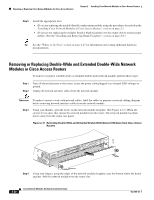
Chapter 2 Installing Cisco Network Modules in Cisco Access Routers Installing Cisco Network Modules in Cisco Access Routers To remove slot adapters from network module slots, perform the following steps: Step 1 Step 2 Step 3 Step 4 Remove any installed network modules and blank faceplates from the router slot you plan to use. Using a number 1 Phillips or small flat-head screwdriver, loosen the captive screw on the slot adapter. (See Figure 2-7.) Slide the slot adapter from the slot. Proceed with hardware configuration tasks as listed in Table 2-3 and Table 2-4. Installing Single-Wide, Extended Single-Wide, and Extension Voice Network Modules in Cisco Access Routers Network modules can be installed either before or after mounting the router, whichever is more convenient. To install a network module, follow these steps: Step 1 Turn off electrical power to the router. Leave the power cable plugged in to channel ESD voltages to ground. (For the Cisco MWR 1941-DC router) Turn off power by turning the DC power source circuit breaker to OFF. Tape the circuit breaker in the OFF position. To channel ESD voltages to ground, do not remove the wire from the ground lug. Warning Before performing any of the following procedures, ensure that power is removed from the DC circuit. To ensure that all power is OFF, locate the circuit breaker on the panel board that services the DC circuit, switch the circuit breaker to the OFF position, and tape the switch handle of the circuit breaker in the OFF position. Statement 7 Step 2 Step 3 Remove all network cables, including telephone cables, from the rear panel of the router. Remove the blank faceplates installed over the slot you intend to use. (See the "Installing and Removing Blank Faceplates" section on page 2-6.) Tip Save blank faceplates for future use. Step 4 Step 5 (For certain Cisco routers) Prepare the slot for the network module form factor you are installing. (See the "Preparing Cisco Router Slots for Network Module Installation" section on page 2-8.) Align the network module with the guides in the chassis walls or slot divider and slide it gently into the slot. (See Figure 2-10.) OL-2485-20 Cisco Network Modules Hardware Installation Guide 2-15
-
 1
1 -
2
-
3
-
4
-
5
-
6
-
7
-
8
-
9
-
10
-
11
-
12
-
13
-
14
-
15
-
16
-
17
-
18
-
19
-
20
-
21
-
22
-
23
-
24
-
25
-
26
-
27
-
28
-
29
-
30
-
31
-
32
-
33
-
34
-
35
-
36
-
37
-
38
-
39
-
40
-
41
-
42
-
43
-
44
-
45
-
46
-
47
-
48
-
49
-
50
-
51
-
52
-
53
-
54
-
55
-
56
-
57
-
 58
58 -
 59
59 -
 60
60 -
 61
61 -
 62
62 -
 63
63 -
 64
64 -
 65
65 -
 66
66 -
 67
67 -
 68
68 -
69
-
70
-
71
-
72
-
73
-
74
-
75
-
76
-
77
-
78
-
79
-
80
-
81
-
82
-
83
-
84
-
85
-
86
-
87
-
88
-
89
-
90
-
91
-
92
-
93
-
94
-
95
-
96
-
97
-
98
-
99
-
100
-
101
-
102
-
103
-
104
-
105
-
106
-
107
-
108
-
109
-
110
-
111
-
112
-
113
-
114
-
115
-
116
-
117
-
118
-
119
-
120
-
121
-
122
-
123
-
124
-
125
-
126
-
127
-
128
-
129
-
130
-
131
-
132
-
133
-
134
-
135
-
136
-
137
-
138
-
139
-
140
-
141
-
142
-
143
-
144
-
145
-
146
-
147
-
148
-
149
-
150
-
151
-
152
-
153
-
154
-
155
-
156
-
157
-
158
-
159
-
160
-
161
-
162
-
163
-
164
-
165
-
166
-
167
-
168
-
169
-
170
-
171
-
172
-
173
-
174
-
175
-
176
-
177
-
178
-
179
-
180
-
181
-
182
-
183
-
184
-
185
-
186
-
187
-
188
-
189
-
190
-
191
-
192
-
193
-
194
-
195
-
196
-
197
-
198
-
199
-
200
-
201
-
202
-
203
-
204
-
205
-
206
-
207
-
208
-
209
-
210
-
211
-
212
-
213
-
214
-
215
-
216
-
217
-
218
-
219
-
220
-
221
-
222
-
223
-
224
-
225
-
226
-
227
-
228
-
229
-
230
-
231
-
232
-
233
-
234
-
235
-
236
-
237
-
238
-
239
-
240
-
241
-
242
-
243
-
244
-
245
-
246
-
247
-
248
-
249
-
250
-
251
-
252
-
253
-
254
-
255
-
256
-
257
-
258
-
259
-
260
-
261
-
262
-
263
-
264
-
265
-
266
-
267
-
268
-
269
-
270
-
271
-
272
-
273
-
274
-
275
-
276
-
277
-
278
-
279
-
280
-
281
-
282
-
283
-
284
-
285
-
286
-
287
-
288
-
289
-
290
-
291
-
292
-
293
-
294
-
295
-
296
-
297
-
298
-
299
-
300
-
301
-
302
-
303
-
304
-
305
-
306
-
307
-
308
-
309
-
310
-
311
-
312
-
313
-
314
-
315
-
316
-
317
-
318
-
319
-
320
-
321
-
322
-
323
-
324
-
325
-
326
-
327
-
328
-
329
-
330
-
331
-
332
-
333
-
334
-
335
-
336
-
337
-
338
-
339
-
340
-
341
-
342
-
343
-
344
-
345
-
346
-
347
-
348
-
349
-
350
-
351
-
352
-
353
-
354
-
355
-
356
-
357
-
358
-
359
-
360
-
361
-
362
-
363
-
364
-
365
-
366
-
367
-
368
-
369
-
370
-
371
-
372
-
373
-
374
-
375
-
376
-
377
-
378
-
379
-
380
-
381
-
382
-
383
-
384
-
385
-
386
-
387
-
388
-
389
-
390
-
391
-
392
-
393
-
394
-
395
-
396
-
397
-
398
-
399
-
400
-
401
-
402
-
403
-
404
-
405
-
406
-
407
-
408
-
409
-
410
-
411
-
412
-
413
-
414
-
415
-
416
-
417
-
418
 |
 |
