Cisco 3825 Hardware Installation Guide - Page 313
Connecting Alarm Interface Controller Network Modules - over temperature
 |
UPC - 746320981505
View all Cisco 3825 manuals
Add to My Manuals
Save this manual to your list of manuals |
Page 313 highlights
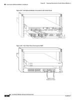
29 C H A P T E R Connecting Alarm Interface Controller Network Modules This chapter describes how to install the alarm interface controller (AIC) network module and contains the following sections: • Alarm Interface Controller Network Module, page 29-1 • Connecting the AIC Network Module to the Network, page 29-2 • AIC Network Module LEDs, page 29-8 Tip To determine whether your router supports a specific network module, see Table 1-6 on page 1-16. Alarm Interface Controller Network Module The AIC network module, shown in Figure 29-1, supports 64 alarm inputs. Fifty-six alarm inputs are discrete and can operate on dry contact closure when a patch panel is used. The last eight alarm inputs can be provisioned to accept analog inputs. The AIC network module has 16 control relay outputs. The AIC network module can be connected to a patch panel. The patch panel provides the bias to the circuit. The analog alarm inputs can be configured to monitor either DC voltage or current. The AIC can measure voltage from -60 to 60 V or current from 0 to 20 mA. The control relay can be operated to turn an external device on or off. When an event is detected, notification messages are sent to the Operations Support System (OSS) in the network operation center (NOC). These alarm inputs are configured in Cisco IOS software. Some reportable events include: • Equipment alarm • Building intrusion (door/window) • Temperature threshold violation • Voltage fluctuation The AIC network module converts relay contact alarm signals to TL1 and SNMP message formats, providing TL1 over TCP/IP and SNMP protocols. All the contact closure-related alarms are routed and reported through the existing OSS and the associated OSS networks. With this network module, the Cisco router sends the TL1 or SNMP messages to the OSS autonomously or in response to TL1 or SNMP commands from the OSS. OL-2485-20 Cisco Network Modules Hardware Installation Guide 29-1
-
 1
1 -
2
-
3
-
4
-
5
-
6
-
7
-
8
-
9
-
10
-
11
-
12
-
13
-
14
-
15
-
16
-
17
-
18
-
19
-
20
-
21
-
22
-
23
-
24
-
25
-
26
-
27
-
28
-
29
-
30
-
31
-
32
-
33
-
34
-
35
-
36
-
37
-
38
-
39
-
40
-
41
-
42
-
43
-
44
-
45
-
46
-
47
-
48
-
49
-
50
-
51
-
52
-
53
-
54
-
55
-
56
-
57
-
58
-
59
-
60
-
61
-
62
-
63
-
64
-
65
-
66
-
67
-
68
-
69
-
70
-
71
-
72
-
73
-
74
-
75
-
76
-
77
-
78
-
79
-
80
-
81
-
82
-
83
-
84
-
85
-
86
-
87
-
88
-
89
-
90
-
91
-
92
-
93
-
94
-
95
-
96
-
97
-
98
-
99
-
100
-
101
-
102
-
103
-
104
-
105
-
106
-
107
-
108
-
109
-
110
-
111
-
112
-
113
-
114
-
115
-
116
-
117
-
118
-
119
-
120
-
121
-
122
-
123
-
124
-
125
-
126
-
127
-
128
-
129
-
130
-
131
-
132
-
133
-
134
-
135
-
136
-
137
-
138
-
139
-
140
-
141
-
142
-
143
-
144
-
145
-
146
-
147
-
148
-
149
-
150
-
151
-
152
-
153
-
154
-
155
-
156
-
157
-
158
-
159
-
160
-
161
-
162
-
163
-
164
-
165
-
166
-
167
-
168
-
169
-
170
-
171
-
172
-
173
-
174
-
175
-
176
-
177
-
178
-
179
-
180
-
181
-
182
-
183
-
184
-
185
-
186
-
187
-
188
-
189
-
190
-
191
-
192
-
193
-
194
-
195
-
196
-
197
-
198
-
199
-
200
-
201
-
202
-
203
-
204
-
205
-
206
-
207
-
208
-
209
-
210
-
211
-
212
-
213
-
214
-
215
-
216
-
217
-
218
-
219
-
220
-
221
-
222
-
223
-
224
-
225
-
226
-
227
-
228
-
229
-
230
-
231
-
232
-
233
-
234
-
235
-
236
-
237
-
238
-
239
-
240
-
241
-
242
-
243
-
244
-
245
-
246
-
247
-
248
-
249
-
250
-
251
-
252
-
253
-
254
-
255
-
256
-
257
-
258
-
259
-
260
-
261
-
262
-
263
-
264
-
265
-
266
-
267
-
268
-
269
-
270
-
271
-
272
-
273
-
274
-
275
-
276
-
277
-
278
-
279
-
280
-
281
-
282
-
283
-
284
-
285
-
286
-
287
-
288
-
289
-
290
-
291
-
292
-
293
-
294
-
295
-
296
-
297
-
298
-
299
-
300
-
301
-
302
-
303
-
304
-
305
-
306
-
307
-
 308
308 -
 309
309 -
 310
310 -
 311
311 -
 312
312 -
 313
313 -
 314
314 -
 315
315 -
 316
316 -
 317
317 -
 318
318 -
319
-
320
-
321
-
322
-
323
-
324
-
325
-
326
-
327
-
328
-
329
-
330
-
331
-
332
-
333
-
334
-
335
-
336
-
337
-
338
-
339
-
340
-
341
-
342
-
343
-
344
-
345
-
346
-
347
-
348
-
349
-
350
-
351
-
352
-
353
-
354
-
355
-
356
-
357
-
358
-
359
-
360
-
361
-
362
-
363
-
364
-
365
-
366
-
367
-
368
-
369
-
370
-
371
-
372
-
373
-
374
-
375
-
376
-
377
-
378
-
379
-
380
-
381
-
382
-
383
-
384
-
385
-
386
-
387
-
388
-
389
-
390
-
391
-
392
-
393
-
394
-
395
-
396
-
397
-
398
-
399
-
400
-
401
-
402
-
403
-
404
-
405
-
406
-
407
-
408
-
409
-
410
-
411
-
412
-
413
-
414
-
415
-
416
-
417
-
418
 |
 |
