Cisco 3825 Hardware Installation Guide - Page 218
Requirements for Installing Two Ethernet Switch Network Modules in a Single Chassis, Power - vlan
 |
UPC - 746320981505
View all Cisco 3825 manuals
Add to My Manuals
Save this manual to your list of manuals |
Page 218 highlights
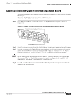
Requirements for Installing Two Ethernet Switch Network Modules in a Single Chassis Chapter 17 Connecting Ethernet Switch Network Modules Figure 17-1 16-Port Ethernet Switch Network Module NMESW- 15x FastEthernet Ports 8x 16 7x 15x 7x 14x 6x 13x 5x 12x 4x 11x 3x 10x 2x 9x 1x 0x 8x 0x -48V Ext Pwr GE 10/100/ 1000 Base-Tx EN 62347 72004 Figure 17-2 36-Port Ethernet Switch Network Module NMDESW36 35x GE1 FastEthernet Ports 18x 10/100/1000 Base-Tx 17x 35x 17x 34x 16x 33x 15x 32x 14x 31x 13x 30x 12x 29x 11x 28x 10x 27x 9x 26x 8x 25x 17 24x 6x 23x 5x 22x 4x 21x 3x 20x 2x 0x 19x 1x 18x 0x -48V Ext Pwr GE0 10/100/ 1000 Base-Tx EN Requirements for Installing Two Ethernet Switch Network Modules in a Single Chassis A maximum of two Ethernet switch network modules can be installed in a single chassis. If two Ethernet switch network modules of any type are installed in the same chassis, the following configuration requirements must be met: • Both Ethernet switch network modules must have an optional Gigabit Ethernet expansion board installed. • An Ethernet crossover cable is connected to the two Ethernet switch network modules using the optional Gigabit Ethernet expansion board ports. • Intrachassis stacking for the the optional Gigabit Ethernet expansion board ports is configured. For information about intrachassis stacking configuration, see the 16- and 36-Port Ethernet Switch Module for Cisco 2600 Series, Cisco 3600 Series, and Cisco 3700 series feature document. Without this configuration and connection, duplications will occur in the VLAN databases, and unexpected packet handling may occur. Power Considerations The Ethernet switch network module supports inline powering of IP telephones with -48-V power. This allows IP phones to be plugged into the standard RJ-45 jack and be powered from this source rather than having a separate plug into an AC wall outlet. The Ethernet switch network module requires delivery of -48-V power to the network module in order to provide inline powering of IP telephones. Cisco 2800 series, Cisco 3700 series, and Cisco 3800 series routers supply -48 V power internally (with AC-IP power supplies) to the Ethernet switch service modules. To support Cisco 2600 series and Cisco 3600 series routers, which do not supply -48-V internal power, the network module has an external connector for connection to an external -48-V power supply. The Ethernet switch network module distributes the -48-V power to each of the Ethernet ports that are configured for line power. Each port can be independently configured for line power. 17-2 Cisco Network Modules Hardware Installation Guide OL-2485-20
-
 1
1 -
2
-
3
-
4
-
5
-
6
-
7
-
8
-
9
-
10
-
11
-
12
-
13
-
14
-
15
-
16
-
17
-
18
-
19
-
20
-
21
-
22
-
23
-
24
-
25
-
26
-
27
-
28
-
29
-
30
-
31
-
32
-
33
-
34
-
35
-
36
-
37
-
38
-
39
-
40
-
41
-
42
-
43
-
44
-
45
-
46
-
47
-
48
-
49
-
50
-
51
-
52
-
53
-
54
-
55
-
56
-
57
-
58
-
59
-
60
-
61
-
62
-
63
-
64
-
65
-
66
-
67
-
68
-
69
-
70
-
71
-
72
-
73
-
74
-
75
-
76
-
77
-
78
-
79
-
80
-
81
-
82
-
83
-
84
-
85
-
86
-
87
-
88
-
89
-
90
-
91
-
92
-
93
-
94
-
95
-
96
-
97
-
98
-
99
-
100
-
101
-
102
-
103
-
104
-
105
-
106
-
107
-
108
-
109
-
110
-
111
-
112
-
113
-
114
-
115
-
116
-
117
-
118
-
119
-
120
-
121
-
122
-
123
-
124
-
125
-
126
-
127
-
128
-
129
-
130
-
131
-
132
-
133
-
134
-
135
-
136
-
137
-
138
-
139
-
140
-
141
-
142
-
143
-
144
-
145
-
146
-
147
-
148
-
149
-
150
-
151
-
152
-
153
-
154
-
155
-
156
-
157
-
158
-
159
-
160
-
161
-
162
-
163
-
164
-
165
-
166
-
167
-
168
-
169
-
170
-
171
-
172
-
173
-
174
-
175
-
176
-
177
-
178
-
179
-
180
-
181
-
182
-
183
-
184
-
185
-
186
-
187
-
188
-
189
-
190
-
191
-
192
-
193
-
194
-
195
-
196
-
197
-
198
-
199
-
200
-
201
-
202
-
203
-
204
-
205
-
206
-
207
-
208
-
209
-
210
-
211
-
212
-
 213
213 -
 214
214 -
 215
215 -
 216
216 -
 217
217 -
 218
218 -
 219
219 -
 220
220 -
 221
221 -
 222
222 -
 223
223 -
224
-
225
-
226
-
227
-
228
-
229
-
230
-
231
-
232
-
233
-
234
-
235
-
236
-
237
-
238
-
239
-
240
-
241
-
242
-
243
-
244
-
245
-
246
-
247
-
248
-
249
-
250
-
251
-
252
-
253
-
254
-
255
-
256
-
257
-
258
-
259
-
260
-
261
-
262
-
263
-
264
-
265
-
266
-
267
-
268
-
269
-
270
-
271
-
272
-
273
-
274
-
275
-
276
-
277
-
278
-
279
-
280
-
281
-
282
-
283
-
284
-
285
-
286
-
287
-
288
-
289
-
290
-
291
-
292
-
293
-
294
-
295
-
296
-
297
-
298
-
299
-
300
-
301
-
302
-
303
-
304
-
305
-
306
-
307
-
308
-
309
-
310
-
311
-
312
-
313
-
314
-
315
-
316
-
317
-
318
-
319
-
320
-
321
-
322
-
323
-
324
-
325
-
326
-
327
-
328
-
329
-
330
-
331
-
332
-
333
-
334
-
335
-
336
-
337
-
338
-
339
-
340
-
341
-
342
-
343
-
344
-
345
-
346
-
347
-
348
-
349
-
350
-
351
-
352
-
353
-
354
-
355
-
356
-
357
-
358
-
359
-
360
-
361
-
362
-
363
-
364
-
365
-
366
-
367
-
368
-
369
-
370
-
371
-
372
-
373
-
374
-
375
-
376
-
377
-
378
-
379
-
380
-
381
-
382
-
383
-
384
-
385
-
386
-
387
-
388
-
389
-
390
-
391
-
392
-
393
-
394
-
395
-
396
-
397
-
398
-
399
-
400
-
401
-
402
-
403
-
404
-
405
-
406
-
407
-
408
-
409
-
410
-
411
-
412
-
413
-
414
-
415
-
416
-
417
-
418
 |
 |
