Cisco 3825 Hardware Installation Guide - Page 361
Replacing the NM-1VSAT-GILAT Network Module in a Router, What to Do Next - router ip and password
 |
UPC - 746320981505
View all Cisco 3825 manuals
Add to My Manuals
Save this manual to your list of manuals |
Page 361 highlights
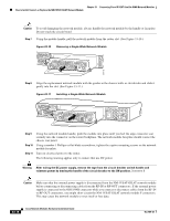
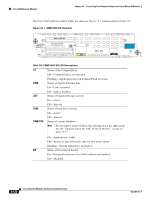
Chapter 33 Connecting Cisco IP VSAT Satellite WAN Network Modules How to Install, Connect, or Replace the NM-1VSAT-GILAT Network Module What to Do Next Configure the initial VSAT parameters for the new NM-1VSAT-GILAT network module. See the Cisco IP VSAT Satellite WAN Network Module (NM-1VSAT-GILAT) Cisco IOS feature module. Note Satellite initial configuration mode can only be accessed by a password that is unique to each NM-1VSAT-GILAT network module. If an installation technician does not configure the initial VSAT parameters, then your satellite service provider will provide the password for your new NM-1VSAT-GILAT network module. Replacing the NM-1VSAT-GILAT Network Module in a Router This section describes how to replace the NM-1VSAT-GILAT network module when your router does not support online insertion and removal (OIR). If your router supports OIR, do not perform this task. Instead, go to the "Performing Online Insertion and Removal of the NM-1VSAT-GILAT Network Module" section on page 33-14. To replace the NM-1VSAT-GILAT network module in your router, follow these steps: Step 1 Disconnect the power supply cable from the ODU PWR connector on the NM-1VSAT-GILAT network module. Caution Make sure that the external power supply is disconnected from the NM-1VSAT-GILAT network module before connecting or disconnecting cables from the RF-IN or RF-OUT connectors. If the external power supply is connected to the ODU PWR connector while you connect or disconnect cables from the RF-IN or RF-OUT connectors, you might short-circuit the NM-1VSAT-GILAT network module F connectors. This may cause the network module to reset itself or lose data. Step 2 Step 3 Step 4 (Optional but recommended) Label the RF cables "RF-IN" and "RF-OUT." Disconnect the cables from the RF-IN and RF-OUT connectors on the NM-1VSAT-GILAT network module. Turn off electrical power to the router. Leave the power cable plugged in to channel ESD voltages to ground. The following warning applies only to routers that use DC power. Warning Before performing any of the following procedures, ensure that power is removed from the DC circuit. To ensure that all power is OFF, locate the circuit breaker on the panel board that services the DC circuit, switch the circuit breaker to the OFF position, and tape the switch handle of the circuit breaker in the OFF position. Statement 7 Timesaver Label the cables or prepare a network cabling diagram before removing cables. Step 5 Step 6 Remove all network cables, including telephone cables, from the rear panel of the router. Using a number 1 Phillips or flat-blade screwdriver, loosen the captive mounting screws on the NM-1VSAT-GILAT network module faceplate. OL-2485-20 Cisco Network Modules Hardware Installation Guide 33-17
-
 1
1 -
2
-
3
-
4
-
5
-
6
-
7
-
8
-
9
-
10
-
11
-
12
-
13
-
14
-
15
-
16
-
17
-
18
-
19
-
20
-
21
-
22
-
23
-
24
-
25
-
26
-
27
-
28
-
29
-
30
-
31
-
32
-
33
-
34
-
35
-
36
-
37
-
38
-
39
-
40
-
41
-
42
-
43
-
44
-
45
-
46
-
47
-
48
-
49
-
50
-
51
-
52
-
53
-
54
-
55
-
56
-
57
-
58
-
59
-
60
-
61
-
62
-
63
-
64
-
65
-
66
-
67
-
68
-
69
-
70
-
71
-
72
-
73
-
74
-
75
-
76
-
77
-
78
-
79
-
80
-
81
-
82
-
83
-
84
-
85
-
86
-
87
-
88
-
89
-
90
-
91
-
92
-
93
-
94
-
95
-
96
-
97
-
98
-
99
-
100
-
101
-
102
-
103
-
104
-
105
-
106
-
107
-
108
-
109
-
110
-
111
-
112
-
113
-
114
-
115
-
116
-
117
-
118
-
119
-
120
-
121
-
122
-
123
-
124
-
125
-
126
-
127
-
128
-
129
-
130
-
131
-
132
-
133
-
134
-
135
-
136
-
137
-
138
-
139
-
140
-
141
-
142
-
143
-
144
-
145
-
146
-
147
-
148
-
149
-
150
-
151
-
152
-
153
-
154
-
155
-
156
-
157
-
158
-
159
-
160
-
161
-
162
-
163
-
164
-
165
-
166
-
167
-
168
-
169
-
170
-
171
-
172
-
173
-
174
-
175
-
176
-
177
-
178
-
179
-
180
-
181
-
182
-
183
-
184
-
185
-
186
-
187
-
188
-
189
-
190
-
191
-
192
-
193
-
194
-
195
-
196
-
197
-
198
-
199
-
200
-
201
-
202
-
203
-
204
-
205
-
206
-
207
-
208
-
209
-
210
-
211
-
212
-
213
-
214
-
215
-
216
-
217
-
218
-
219
-
220
-
221
-
222
-
223
-
224
-
225
-
226
-
227
-
228
-
229
-
230
-
231
-
232
-
233
-
234
-
235
-
236
-
237
-
238
-
239
-
240
-
241
-
242
-
243
-
244
-
245
-
246
-
247
-
248
-
249
-
250
-
251
-
252
-
253
-
254
-
255
-
256
-
257
-
258
-
259
-
260
-
261
-
262
-
263
-
264
-
265
-
266
-
267
-
268
-
269
-
270
-
271
-
272
-
273
-
274
-
275
-
276
-
277
-
278
-
279
-
280
-
281
-
282
-
283
-
284
-
285
-
286
-
287
-
288
-
289
-
290
-
291
-
292
-
293
-
294
-
295
-
296
-
297
-
298
-
299
-
300
-
301
-
302
-
303
-
304
-
305
-
306
-
307
-
308
-
309
-
310
-
311
-
312
-
313
-
314
-
315
-
316
-
317
-
318
-
319
-
320
-
321
-
322
-
323
-
324
-
325
-
326
-
327
-
328
-
329
-
330
-
331
-
332
-
333
-
334
-
335
-
336
-
337
-
338
-
339
-
340
-
341
-
342
-
343
-
344
-
345
-
346
-
347
-
348
-
349
-
350
-
351
-
352
-
353
-
354
-
355
-
 356
356 -
 357
357 -
 358
358 -
 359
359 -
 360
360 -
 361
361 -
 362
362 -
 363
363 -
 364
364 -
 365
365 -
 366
366 -
367
-
368
-
369
-
370
-
371
-
372
-
373
-
374
-
375
-
376
-
377
-
378
-
379
-
380
-
381
-
382
-
383
-
384
-
385
-
386
-
387
-
388
-
389
-
390
-
391
-
392
-
393
-
394
-
395
-
396
-
397
-
398
-
399
-
400
-
401
-
402
-
403
-
404
-
405
-
406
-
407
-
408
-
409
-
410
-
411
-
412
-
413
-
414
-
415
-
416
-
417
-
418
 |
 |
