Dell External OEMR R620 Owners Manual - Page 35
Installing System Components, Recommended Tools, Front Bezel (Optional), Removing The Front Bezel
 |
View all Dell External OEMR R620 manuals
Add to My Manuals
Save this manual to your list of manuals |
Page 35 highlights
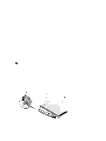
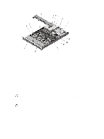
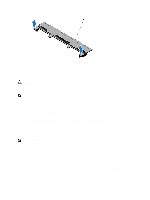
3 Installing System Components Recommended Tools You may need the following items to perform the procedures in this section: • Key to the system keylock • #1 and #2 Phillips screwdrivers • T10 and T15 Torx screwdrivers • Wrist grounding strap connected to ground Following tools are required for assembling cables for a DC power supply unit (PSU), when available: • Wire-stripper pliers capable of removing insulation from size 10 AWG solid or stranded, insulated copper wire • AMP 90871-1 hand-crimping tool or equivalent NOTE: Use alpha wire part number 3080 or equivalent (65/30 stranding). Front Bezel (Optional) Removing The Front Bezel 1. Unlock the keylock at the left end of the bezel. 2. Lift the release latch next to the keylock. 3. Rotate the left end of the bezel away from the front panel. 4. Unhook the right end of the bezel and pull the bezel away from the system. Figure 10. Removing and Installing the Front Bezel 35
-
 1
1 -
2
-
3
-
4
-
5
-
6
-
7
-
8
-
9
-
10
-
11
-
12
-
13
-
14
-
15
-
16
-
17
-
18
-
19
-
20
-
21
-
22
-
23
-
24
-
25
-
26
-
27
-
28
-
29
-
 30
30 -
 31
31 -
 32
32 -
 33
33 -
 34
34 -
 35
35 -
 36
36 -
 37
37 -
 38
38 -
 39
39 -
 40
40 -
41
-
42
-
43
-
44
-
45
-
46
-
47
-
48
-
49
-
50
-
51
-
52
-
53
-
54
-
55
-
56
-
57
-
58
-
59
-
60
-
61
-
62
-
63
-
64
-
65
-
66
-
67
-
68
-
69
-
70
-
71
-
72
-
73
-
74
-
75
-
76
-
77
-
78
-
79
-
80
-
81
-
82
-
83
-
84
-
85
-
86
-
87
-
88
-
89
-
90
-
91
-
92
-
93
-
94
-
95
-
96
-
97
-
98
-
99
-
100
-
101
-
102
-
103
-
104
-
105
-
106
-
107
-
108
-
109
-
110
-
111
-
112
-
113
-
114
-
115
-
116
-
117
-
118
-
119
-
120
-
121
-
122
-
123
-
124
-
125
-
126
-
127
-
128
-
129
-
130
-
131
-
132
-
133
 |
 |
