Dell External OEMR R620 Owners Manual - Page 71
Power Supplies, the center of the topside of the new processor.
 |
View all Dell External OEMR R620 manuals
Add to My Manuals
Save this manual to your list of manuals |
Page 71 highlights
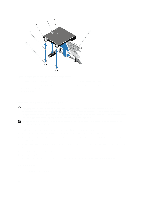
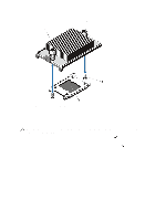
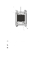
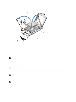
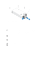
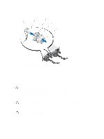
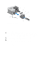
3. Open the system. 4. Remove the cooling shroud. WARNING: The heat sink and processor are hot to the touch for some time after the system has been powered down. Allow the heat sink and processor to cool before handling them. CAUTION: Never remove the heat sink from a processor unless you intend to remove the processor. The heat sink is necessary to maintain proper thermal conditions. 5. Remove the heat sink/heat-sink blank and processor/processor blank, as applicable. NOTE: The procedure to remove the heat-sink blank or processor blank is similar to removing a heat-sink or processor. 6. Unpack the new processor. 7. Align the processor with the socket keys on the ZIF socket. CAUTION: Positioning the processor incorrectly can permanently damage the system board or the processor. Be careful not to bend the pins in the socket. CAUTION: Do not use force to seat the processor. When the processor is positioned correctly, it engages easily into the socket. 8. With the release levers on the processor socket in the open position, align pin 1 of the processor, using pin 1 position guide on the socket, as reference and set the processor lightly in the socket. 9. Close the processor shield. 10. Rotate the socket-release lever near the lock icon until it is locked in position. 11. Similarly, rotate the socket-release lever near the unlock icon until it is locked in position. 12. Using a clean lint-free cloth, remove the thermal grease from the heat sink. CAUTION: Applying too much thermal grease can result in excess grease coming in contact with and contaminating the processor socket. 13. Open the grease applicator included with your processor kit and apply all of the thermal grease in the applicator to the center of the topside of the new processor. 14. Place the heat sink on the processor. 15. Using a #2 Phillips screwdriver, tighten the heat-sink retention sockets. 16. Install the cooling shroud. 17. Close the system. 18. Reconnect your system and peripherals to their electrical outlets, and turn on the system. 19. Press to enter the System Setup and check that the processor information matches the new system configuration. 20. Run the system diagnostics to verify that the new processor operates correctly. Power Supplies Your system supports either: • Two 495 W, 750 W, or 1100 W AC power supply modules, or • Two 1100 W DC power supply modules (when available). When two identical power supplies are installed, the power supply configuration is redundant (1 + 1). In redundant mode, power is supplied to the system equally from both power supplies to maximize efficiency. 71
-
 1
1 -
2
-
3
-
4
-
5
-
6
-
7
-
8
-
9
-
10
-
11
-
12
-
13
-
14
-
15
-
16
-
17
-
18
-
19
-
20
-
21
-
22
-
23
-
24
-
25
-
26
-
27
-
28
-
29
-
30
-
31
-
32
-
33
-
34
-
35
-
36
-
37
-
38
-
39
-
40
-
41
-
42
-
43
-
44
-
45
-
46
-
47
-
48
-
49
-
50
-
51
-
52
-
53
-
54
-
55
-
56
-
57
-
58
-
59
-
60
-
61
-
62
-
63
-
64
-
65
-
 66
66 -
 67
67 -
 68
68 -
 69
69 -
 70
70 -
 71
71 -
 72
72 -
 73
73 -
 74
74 -
 75
75 -
 76
76 -
77
-
78
-
79
-
80
-
81
-
82
-
83
-
84
-
85
-
86
-
87
-
88
-
89
-
90
-
91
-
92
-
93
-
94
-
95
-
96
-
97
-
98
-
99
-
100
-
101
-
102
-
103
-
104
-
105
-
106
-
107
-
108
-
109
-
110
-
111
-
112
-
113
-
114
-
115
-
116
-
117
-
118
-
119
-
120
-
121
-
122
-
123
-
124
-
125
-
126
-
127
-
128
-
129
-
130
-
131
-
132
-
133
 |
 |
