Dell External OEMR R620 Owners Manual - Page 76
Removing A DC Power Supply, Assembling the DC Input Power Wires
 |
View all Dell External OEMR R620 manuals
Add to My Manuals
Save this manual to your list of manuals |
Page 76 highlights
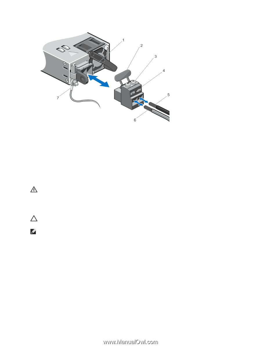
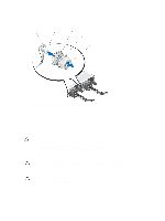
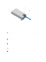
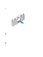
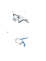
Figure 34. Assembling the DC Input Power Wires 1. DC power socket 2. rubber cap 3. captive screws (2) 4. DC power connector 5. wire -48 V 6. wire RTN 7. grounding wire Removing A DC Power Supply WARNING: For equipment using -(48-60) V DC power supplies, a qualified electrician must perform all connections to DC power and to safety grounds. Do not attempt connecting to DC power or installing grounds yourself. All electrical wiring must comply with applicable local or national codes and practices. Damage due to servicing that is not authorized by Dell is not covered by your warranty. Read and follow all safety instructions that came with the product. CAUTION: The system requires one power supply for normal operation. On power-redundant systems, remove and replace only one power supply at a time in a system that is powered on. NOTE: You may have to unlatch and lift the optional cable management arm if it interferes with power supply removal. For information about the cable management arm, see the system's rack documentation. 1. Disconnect the power wires from the power source and the connector from the power supply you intend to remove. 2. Disconnect the safety ground wire. 3. Press the release latch and slide the power supply out of the chassis. 76
-
 1
1 -
2
-
3
-
4
-
5
-
6
-
7
-
8
-
9
-
10
-
11
-
12
-
13
-
14
-
15
-
16
-
17
-
18
-
19
-
20
-
21
-
22
-
23
-
24
-
25
-
26
-
27
-
28
-
29
-
30
-
31
-
32
-
33
-
34
-
35
-
36
-
37
-
38
-
39
-
40
-
41
-
42
-
43
-
44
-
45
-
46
-
47
-
48
-
49
-
50
-
51
-
52
-
53
-
54
-
55
-
56
-
57
-
58
-
59
-
60
-
61
-
62
-
63
-
64
-
65
-
66
-
67
-
68
-
69
-
70
-
 71
71 -
 72
72 -
 73
73 -
 74
74 -
 75
75 -
 76
76 -
 77
77 -
 78
78 -
 79
79 -
 80
80 -
 81
81 -
82
-
83
-
84
-
85
-
86
-
87
-
88
-
89
-
90
-
91
-
92
-
93
-
94
-
95
-
96
-
97
-
98
-
99
-
100
-
101
-
102
-
103
-
104
-
105
-
106
-
107
-
108
-
109
-
110
-
111
-
112
-
113
-
114
-
115
-
116
-
117
-
118
-
119
-
120
-
121
-
122
-
123
-
124
-
125
-
126
-
127
-
128
-
129
-
130
-
131
-
132
-
133
 |
 |