Dell External OEMR R620 Owners Manual - Page 89
Removing and Installing the Control Panel
 |
View all Dell External OEMR R620 manuals
Add to My Manuals
Save this manual to your list of manuals |
Page 89 highlights
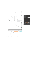
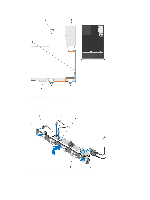
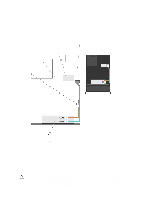
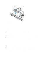
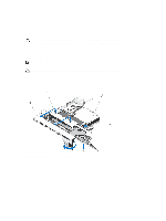
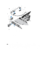
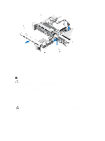
1. If installed, remove the front bezel. 2. Turn off the system, including any attached peripherals, and disconnect the system from the electrical outlet and peripherals. 3. Open the system. CAUTION: The display module connector is a ZIF (zero insertion force) connector. Ensure that the locking tab on the connector is released before removal and insertion. The locking tab must be engaged after insertion. 4. Disconnect the display module cable from the control panel board. 5. Using a #1 Philips screwdriver, remove the screw (located at the bottom of the chassis) that secures the control module to the chassis. NOTE: Apart from the screw, the control panel has three tabs (one on the left and two tabs on top) that secure it to the chassis. CAUTION: Applying excessive force while pulling upward may damage the control panel. 6. Hold the top edge of the control panel at the corners and pull upward until the control panel tabs release. 7. Hold the right edge of the control panel and rotate it toward the left till it releases from the chassis. 8. Pull the control panel away from the chassis. Figure 49. Removing and Installing the Control Panel 1. control panel 2. notches on chassis front wall 3. display module ZIF connector 4. display module cable 5. screw 89
-
 1
1 -
2
-
3
-
4
-
5
-
6
-
7
-
8
-
9
-
10
-
11
-
12
-
13
-
14
-
15
-
16
-
17
-
18
-
19
-
20
-
21
-
22
-
23
-
24
-
25
-
26
-
27
-
28
-
29
-
30
-
31
-
32
-
33
-
34
-
35
-
36
-
37
-
38
-
39
-
40
-
41
-
42
-
43
-
44
-
45
-
46
-
47
-
48
-
49
-
50
-
51
-
52
-
53
-
54
-
55
-
56
-
57
-
58
-
59
-
60
-
61
-
62
-
63
-
64
-
65
-
66
-
67
-
68
-
69
-
70
-
71
-
72
-
73
-
74
-
75
-
76
-
77
-
78
-
79
-
80
-
81
-
82
-
83
-
 84
84 -
 85
85 -
 86
86 -
 87
87 -
 88
88 -
 89
89 -
 90
90 -
 91
91 -
 92
92 -
 93
93 -
 94
94 -
95
-
96
-
97
-
98
-
99
-
100
-
101
-
102
-
103
-
104
-
105
-
106
-
107
-
108
-
109
-
110
-
111
-
112
-
113
-
114
-
115
-
116
-
117
-
118
-
119
-
120
-
121
-
122
-
123
-
124
-
125
-
126
-
127
-
128
-
129
-
130
-
131
-
132
-
133
 |
 |
