Dell PowerConnect 5448 User's Guide - Page 34
Installing the Device without a Rack, Connecting the Device, Connecting a Device to a Terminal - flow control
 |
View all Dell PowerConnect 5448 manuals
Add to My Manuals
Save this manual to your list of manuals |
Page 34 highlights
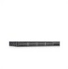
4 Insert the unit into the 19-inch rack ensuring the rack-mounting holes on the device line up to the mounting hole on the rack. 5 Secure the unit to the rack with the rack screws (not provided). Fasten the lower pair of screws before the upper pair of screws. This ensures that the weight of the unit is evenly distributed during installation. Ensure that the ventilation holes are not obstructed. Installing the Device without a Rack The device must be installed on a flat surface if it is not installed on a rack. The surface must be able to support the weight of the device and the device cables. 1 Install rubber feet provided with the device. 2 Set the device on a flat surface, while leaving 2 inches (5.08cm) on each side and 5 inches (12.7cm) at the back. 3 Ensure that the device has proper ventilation. Connecting the Device To configure the device, the device must be connected to a terminal. Connecting a Device to a Terminal The device provides a Console port, that enables a connection to a terminal desktop system running terminal emulation software for monitoring and configuring the device. The Console port connector is a male DB-9 connector, implemented as a data terminal equipment (DTE) connector. To use the Console port, the following is required: • VT100 compatible terminal or a desktop or portable system with a serial port and running VT100 terminal emulation software. • A RS-232 crossover cable with a female DB-9 connector for the Console port and the appropriate connector for the terminal. To connect a terminal to the device Console port, perform the following: 1 Connect an RS-232 crossover cable to the terminal running VT100 terminal emulation software. 2 Ensure that the terminal emulation software is set as follows: a Select the appropriate serial port (serial port 1 or serial port 2) to connect to the console. b Set the data rate to 9600 baud. c Set the data format to 8 data bits, 1 stop bit, and no parity. d Set flow control to none. e Under Properties, select VT100 for Emulation mode. f Select Terminal keys for Function, Arrow, and Ctrl keys. Ensure that the setting is for Terminal keys (not Windows keys). 34 Installing the PowerConnect Device
-
 1
1 -
2
-
3
-
4
-
5
-
6
-
7
-
8
-
9
-
10
-
11
-
12
-
13
-
14
-
15
-
16
-
17
-
18
-
19
-
20
-
21
-
22
-
23
-
24
-
25
-
26
-
27
-
28
-
 29
29 -
 30
30 -
 31
31 -
 32
32 -
 33
33 -
 34
34 -
 35
35 -
 36
36 -
 37
37 -
 38
38 -
 39
39 -
40
-
41
-
42
-
43
-
44
-
45
-
46
-
47
-
48
-
49
-
50
-
51
-
52
-
53
-
54
-
55
-
56
-
57
-
58
-
59
-
60
-
61
-
62
-
63
-
64
-
65
-
66
-
67
-
68
-
69
-
70
-
71
-
72
-
73
-
74
-
75
-
76
-
77
-
78
-
79
-
80
-
81
-
82
-
83
-
84
-
85
-
86
-
87
-
88
-
89
-
90
-
91
-
92
-
93
-
94
-
95
-
96
-
97
-
98
-
99
-
100
-
101
-
102
-
103
-
104
-
105
-
106
-
107
-
108
-
109
-
110
-
111
-
112
-
113
-
114
-
115
-
116
-
117
-
118
-
119
-
120
-
121
-
122
-
123
-
124
-
125
-
126
-
127
-
128
-
129
-
130
-
131
-
132
-
133
-
134
-
135
-
136
-
137
-
138
-
139
-
140
-
141
-
142
-
143
-
144
-
145
-
146
-
147
-
148
-
149
-
150
-
151
-
152
-
153
-
154
-
155
-
156
-
157
-
158
-
159
-
160
-
161
-
162
-
163
-
164
-
165
-
166
-
167
-
168
-
169
-
170
-
171
-
172
-
173
-
174
-
175
-
176
-
177
-
178
-
179
-
180
-
181
-
182
-
183
-
184
-
185
-
186
-
187
-
188
-
189
-
190
-
191
-
192
-
193
-
194
-
195
-
196
-
197
-
198
-
199
-
200
-
201
-
202
-
203
-
204
-
205
-
206
-
207
-
208
-
209
-
210
-
211
-
212
-
213
-
214
-
215
-
216
-
217
-
218
-
219
-
220
-
221
-
222
-
223
-
224
-
225
-
226
-
227
-
228
-
229
-
230
-
231
-
232
-
233
-
234
-
235
-
236
-
237
-
238
-
239
-
240
-
241
-
242
-
243
-
244
-
245
-
246
-
247
-
248
-
249
-
250
-
251
-
252
-
253
-
254
-
255
-
256
-
257
-
258
-
259
-
260
-
261
-
262
-
263
-
264
-
265
-
266
-
267
-
268
-
269
-
270
-
271
-
272
-
273
-
274
-
275
-
276
-
277
-
278
-
279
-
280
-
281
-
282
-
283
-
284
-
285
-
286
-
287
-
288
-
289
-
290
-
291
-
292
-
293
-
294
-
295
-
296
-
297
-
298
-
299
-
300
-
301
-
302
-
303
-
304
-
305
-
306
-
307
-
308
-
309
-
310
-
311
-
312
-
313
-
314
-
315
-
316
-
317
-
318
-
319
-
320
-
321
-
322
-
323
-
324
-
325
-
326
-
327
-
328
-
329
-
330
-
331
-
332
-
333
-
334
-
335
-
336
-
337
-
338
-
339
-
340
-
341
-
342
-
343
-
344
-
345
-
346
-
347
-
348
-
349
-
350
-
351
-
352
-
353
-
354
-
355
-
356
-
357
-
358
-
359
-
360
-
361
-
362
-
363
-
364
-
365
-
366
-
367
-
368
-
369
-
370
-
371
-
372
-
373
-
374
-
375
-
376
-
377
-
378
-
379
-
380
-
381
-
382
-
383
-
384
-
385
-
386
-
387
-
388
-
389
-
390
-
391
-
392
-
393
-
394
-
395
-
396
-
397
-
398
-
399
-
400
-
401
-
402
-
403
-
404
-
405
-
406
-
407
-
408
-
409
-
410
-
411
-
412
-
413
-
414
-
415
-
416
-
417
-
418
-
419
-
420
-
421
-
422
-
423
-
424
-
425
-
426
-
427
-
428
-
429
-
430
-
431
-
432
-
433
-
434
-
435
-
436
-
437
-
438
-
439
-
440
-
441
-
442
-
443
-
444
 |
 |
