Dell PowerEdge R415 Hardware Owner's Manual
Dell PowerEdge R415 Manual
 |
View all Dell PowerEdge R415 manuals
Add to My Manuals
Save this manual to your list of manuals |
Dell PowerEdge R415 manual content summary:
- Dell PowerEdge R415 | Hardware Owner's Manual - Page 1
Dell PowerEdge R415 Systems Hardware Owner's Manual Regulatory Model E07S Series Regulatory Type E07S003 - Dell PowerEdge R415 | Hardware Owner's Manual - Page 2
potential damage to hardware or loss of data if instructions are not followed. WARNING: A WARNING indicates a potential Dell Inc. is strictly forbidden. Trademarks used in this text: Dell™, the DELL logo, and PowerEdge™ are trademarks of Dell Inc. Microsoft®, Windows®, MS-DOS®, and Windows Server - Dell PowerEdge R415 | Hardware Owner's Manual - Page 3
9 Front-Panel Features and Indicators 10 LCD Panel Features (Optional 12 Hard-Drive Indicator Patterns 16 Back-Panel Features and Indicators 17 Guidelines for Connecting External Devices 19 NIC Indicator Codes 19 Power Indicator Codes 20 Diagnostic Lights (Optional 21 LCD Status Messages 24 - Dell PowerEdge R415 | Hardware Owner's Manual - Page 4
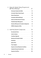
Controller Configuration . . . 76 iDRAC6 Configuration Utility 77 3 Installing System Components 79 Recommended Tools 79 Inside the System 79 Front Bezel (Optional 81 Opening and Closing the System 82 Hard Drives 84 Optical Drive 92 Power Supplies 95 Expansion Card and Expansion-Card Riser - Dell PowerEdge R415 | Hardware Owner's Manual - Page 5
112 iDRAC6 Enterprise Card (Optional 114 VFlash Media (Optional 116 Cooling Fans 117 RAID Battery (Optional 119 System Memory 121 Processors 127 System Battery 133 Control Panel Assembly 135 SAS Backplane 140 Power Distribution Board 142 System Board 144 4 Troubleshooting Your System - Dell PowerEdge R415 | Hardware Owner's Manual - Page 6
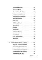
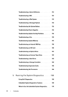
155 Troubleshooting System Cooling Problems 156 Troubleshooting a Fan 156 Troubleshooting System Memory 157 Troubleshooting an Internal USB Key 159 Troubleshooting an SD Card 160 Troubleshooting an Optical Drive 161 Troubleshooting an External Tape Drive 162 Troubleshooting a Hard Drive 163 - Dell PowerEdge R415 | Hardware Owner's Manual - Page 7
Options 171 6 Jumpers and Connectors 173 System Board Jumpers 173 System Board Connectors 174 SAS Backplane Board Connectors 176 Expansion-Card Riser-Board Components and PCIe Buses 177 Power Distribution Board Connectors 178 Disabling a Forgotten Password 179 7 Getting Help 181 Contacting - Dell PowerEdge R415 | Hardware Owner's Manual - Page 8
8 Contents - Dell PowerEdge R415 | Hardware Owner's Manual - Page 9
BMC or iDRAC user documentation at support.dell.com/manuals. Enters the SAS Configuration Utility. For more information, see the SAS adapter documentation at support.dell.com/manuals. Enters the PERC configuration utility. For more information, see the PERC card documentation - Dell PowerEdge R415 | Hardware Owner's Manual - Page 10
a graceful shutdown before power to the system is turned off. Used to troubleshoot software and device driver errors when using certain operating systems. This button can be pressed using the end of a paper clip. Use this button only if directed to do so by qualified support personnel or by the - Dell PowerEdge R415 | Hardware Owner's Manual - Page 11
navigate the control panel LCD menu. NOTE: Depending on the configuration, your system may have either LED diagnostic indicators or an the system has been powered on. The identification buttons on the front and back panels can be used to locate a particular system within a rack. When one of these - Dell PowerEdge R415 | Hardware Owner's Manual - Page 12
Item Indicator, Button, or Icon Connector 7 USB connectors (2) 8 hard-drives (4) 9 System identification panel 10 Optical drive Description Connects USB devices to the system. The ports are USB 2.0-compliant. Up to four 2.5-inch in 3.5-inch HDD hot swap carrier or up to four 3.5-inch - Dell PowerEdge R415 | Hardware Owner's Manual - Page 13
If the system hangs during POST, press and hold the system ID button for more than five seconds to enter BIOS Progress mode. Home Screen The Home screen displays user-configurable information about the system. This screen is displayed during normal system operation when there are no status messages - Dell PowerEdge R415 | Hardware Owner's Manual - Page 14
Menu NOTE: When you select an option in the Setup menu, you must confirm the option before proceeding to the next action. Option Description BMC or DRAC Select DHCP or Static IP to configure the network NOTE: If an iDRAC6 Express card is installed on the system, the BMC option is replaced - Dell PowerEdge R415 | Hardware Owner's Manual - Page 15
If an iDRAC6 Express card is installed on the NOTE: BMC IP supports only IPv4 addresses. replaced by Service tag for the system. Power Displays the power output of the system in BTU/hr or Watts. The display format can be configured in the Set home submenu of the Setup menu. See "Setup - Dell PowerEdge R415 | Hardware Owner's Manual - Page 16
Hard-Drive Indicator Patterns Figure 1-3. Hard-Drive Indicators 1 2 1 hard-drive activity indicator (green) 2 hard-drive status indicator (green and amber) 16 About Your System - Dell PowerEdge R415 | Hardware Owner's Manual - Page 17
-Status Indicator Pattern (RAID Only) Condition Blinks green two times per second Identify drive/preparing for removal Off Drive ready for insertion or removal NOTE: The drive status indicator remains off until all hard-drives are initialized after system power is applied. Drives are not ready - Dell PowerEdge R415 | Hardware Owner's Manual - Page 18
9 System status indicator 10 System identification button 11 Power supply 1(PS1) 12 Power supply 2(PS2) Description Dedicated management port for the optional iDRAC6 Enterprise card. Connects USB devices to the system. The ports are USB 2.0-compliant. Embedded 10/100/1000 NIC connectors. PCI - Dell PowerEdge R415 | Hardware Owner's Manual - Page 19
the documentation for the device specifies otherwise). • Ensure that the appropriate driver for the attached device has been installed on the system. • If necessary to enable ports on your system, use the System Setup program. See "Using the System Setup Program and UEFI Boot Manager" on page 57 - Dell PowerEdge R415 | Hardware Owner's Manual - Page 20
with the flashing indicator. Swapping the opposite power supply to make a matched pair can result in an error condition and unexpected system shutdown. To change from a High Output configuration to an Energy Smart configuration or vice versa, you must power down the system. 20 About Your System - Dell PowerEdge R415 | Hardware Owner's Manual - Page 21
Figure 1-6. Power Supply Status Indicator 1 1 power supply status indicator Diagnostic Lights (Optional) The four diagnostic indicator lights on the system front panel display error codes during system startup. Table 1-1 lists the - Dell PowerEdge R415 | Hardware Owner's Manual - Page 22
Memory failure. See "Troubleshooting System Memory" on page 157. Possible expansion card See "Troubleshooting Expansion failure. Cards" on page 165. Possible video failure. See "Getting Help" on page 181. Hard drive failure. Possible USB failure. Ensure that the diskette drive and hard-drive - Dell PowerEdge R415 | Hardware Owner's Manual - Page 23
system board hardware failure. Possible system resource configuration error. See "Getting Help" on page 181. See "Getting Help" on page 181. Other failure. Ensure that the diskette drive, optical drive, and hard-drives are properly connected. See "Troubleshooting Your System" on page 149 for the - Dell PowerEdge R415 | Hardware Owner's Manual - Page 24
and configuring system management settings, see the OpenManage Server Administrator documentation at support.dell.com/manuals. NOTE: If your system fails to boot, press the event history for the system. • Power cycle-Turn off the system and disconnect it from the electrical outlet; wait approximately - Dell PowerEdge R415 | Hardware Owner's Manual - Page 25
Help" on page 181. Ambient Temp Ambient temperature has See "Troubleshooting exceeds a reached a point outside System Cooling allowed range. of the allowed range. Problems" on page 156. Memory Memory has exceeded Remove AC power to the disabled, temp allowable temperature and system for 10 - Dell PowerEdge R415 | Hardware Owner's Manual - Page 26
regulators failed. Remove AC power to the system for 10 seconds and restart the system. If the problem persists, see "Getting Help" on page 181. CPU # VCORE Regulator failure. Contact Support. Processor voltage regulator Reseat the processor. See failed. "Troubleshooting the Processors" on - Dell PowerEdge R415 | Hardware Owner's Manual - Page 27
an CPU unsupported configuration. configuration. Check CPU or BIOS revision. Ensure that your processors match and conform to the type described in the processor technical specifications outlined in your system's Getting Started Guide. CPU # protocol The system BIOS error. Power has reported - Dell PowerEdge R415 | Hardware Owner's Manual - Page 28
# machine check error. Power cycle AC. The system BIOS has reported a machine check error. Remove AC power to the system for 10 seconds and restart the system. If the problem persists, see "Getting Help" on page 181. Power Supply # Specified power supply See "Troubleshooting (### W) was removed - Dell PowerEdge R415 | Hardware Owner's Manual - Page 29
The processors and Remove AC power to the event. Contact memory have been system for 10 seconds and support. throttled to keep system restart the system. power consumption below the maximum safe level with current power supply configuration. If the problem persists, see "Getting Help" on - Dell PowerEdge R415 | Hardware Owner's Manual - Page 30
and then clear the SEL. Remove AC power to the system for 10 seconds and restart the system. If the problem persists, see "Getting Help" on page 181. Remove and reseat the PCIe expansion cards. If the problem persists, see "Troubleshooting Expansion Cards" on page 165. Remove and reseat the - Dell PowerEdge R415 | Hardware Owner's Manual - Page 31
that resides in PCI configuration space at bus ##, device ##, function ##. Remove and reseat the PCIe expansion cards. If the problem persists, see "Troubleshooting Expansion Cards" on page 165. PCI system error on Slot #. Review & clear SEL. The system BIOS reported Remove and reseat the - Dell PowerEdge R415 | Hardware Owner's Manual - Page 32
that resides in PCI configuration space at bus ##, device ##, function ##. Remove and reseat the PCIe expansion cards. If the problem persists, see "Troubleshooting Expansion Cards" on page 165. PCIe fatal error on Slot #. Review & clear SEL. The system BIOS reported Remove and reseat the - Dell PowerEdge R415 | Hardware Owner's Manual - Page 33
Hard drive ## The specified hard-drive fault. Review has experienced a fault. & clear SEL. See "Troubleshooting a Hard Drive" on page 163. Hard drive ## The specified hard- removed. Check drive has been removed drive. from the system. Information only. iDRAC6 Upgrade The iDRAC6 Express card - Dell PowerEdge R415 | Hardware Owner's Manual - Page 34
"Troubleshooting configured but unusable. System Memory" on unusable. page 157. Check DIMMs. BIOS unable to The system BIOS failed to See "Troubleshooting shadow memory. copy its flash image into System Memory" on Check DIMMs. memory. page 157. CMOS RAM CMOS failure. CMOS failure. Power - Dell PowerEdge R415 | Hardware Owner's Manual - Page 35
system for 10 seconds and restart the system. If the problem persists, see "Getting Help" on page 181. Remove AC power to the system for 10 seconds and restart the system. If the problem persists, see "Getting Help" on page 181. Remove AC power to the system for 10 seconds and restart the system - Dell PowerEdge R415 | Hardware Owner's Manual - Page 36
. cycle AC. POST memory BIOS POST memory test test failure. failure. Check DIMMs. CPU Processor configuration configuration failure. failure. Check screen message. Corrective Actions Remove AC power to the system for 10 seconds and restart the system. If the problem persists, see "Getting - Dell PowerEdge R415 | Hardware Owner's Manual - Page 37
E2021 E2022 E2026 E2110 E2111 Text Causes Corrective Actions Incorrect Incorrect memory memory configuration. configuration. Review User Guide. Check screen for specific error messages. See "Troubleshooting System Memory" on page 157. General failure during POST. Check screen message - Dell PowerEdge R415 | Hardware Owner's Manual - Page 38
many errors. "##" represents the memory module implicated by the BIOS. If the problem persists, see "Troubleshooting System Memory" on page 157. Intrusion detected. Check chassis cover. System cover has been removed. Information only. SEL full. The SEL is full of events Review & clear and is - Dell PowerEdge R415 | Hardware Owner's Manual - Page 39
fully redundant. Reseat the power supplies. See "Troubleshooting Power Supplies" on page 155. If the problem persists, see "Getting Help" on page 181. NOTE: For the full name of an abbreviation or acronym used in this table, see the Glossary at support.dell.com/manuals. About Your System 39 - Dell PowerEdge R415 | Hardware Owner's Manual - Page 40
of a possible problem with the system. to responding. responding to BIOS reboot. Rebooting. communication booting. Alert! Continuing system boot accepts the risk After AC recovery, the iDRAC6 takes longer than normal to boot. that system may power down without warning. Remove AC power - Dell PowerEdge R415 | Hardware Owner's Manual - Page 41
down without warning. The system configuration of processor(s), memory modules, and expansion cards may not be supported by the power supplies. If any system components were just upgraded, return the system to the previous configuration. If the system boots without this warning, then the replaced - Dell PowerEdge R415 | Hardware Owner's Manual - Page 42
the NVRAM_CLR jumper to the default position (pins 3 and 5). See Figure 6-1 for jumper location. Restart the system and re-enter the BIOS settings. See "Using the System Setup Program and UEFI Boot Manager" on page 57. CPU set to minimum frequency. The processor speed may be If not an intentional - Dell PowerEdge R415 | Hardware Owner's Manual - Page 43
Program and available. Use UEFI Boot Manager" on the system setup page 57. program to change the boot mode as needed. Decreasing available memory. Faulty or improperly installed memory modules. Reseat the memory modules. See "Troubleshooting System Memory" on page 157. Embedded NICx and - Dell PowerEdge R415 | Hardware Owner's Manual - Page 44
is operational. See "Troubleshooting a USB Device" on page 150. See "Getting Help" on page 181. This message is usually followed by specific information. Note the information, and take the appropriate action to resolve the problem. Run the System Setup program and review the current settings. See - Dell PowerEdge R415 | Hardware Owner's Manual - Page 45
see "Troubleshooting a USB Device" on page 150. Keyboard fuse has Overcurrent detected at the See "Getting Help" on failed. keyboard connector. page 181. Local keyboard may not work because all user accessible USB ports are disabled. If operating locally, power cycle the system and enter system - Dell PowerEdge R415 | Hardware Owner's Manual - Page 46
, "Troubleshooting a USB Device" on page 150, "Troubleshooting an Optical Drive" on page 161, and "Troubleshooting a Hard Drive" on page 163. See "Using the System Setup Program and UEFI Boot Manager" on page 57 for information on setting the order of boot devices. Check the hard-drive configuration - Dell PowerEdge R415 | Hardware Owner's Manual - Page 47
. If the problem persists, see "Troubleshooting Expansion Cards" on page 165. Read fault. Requested sector not found. The operating system cannot Replace the optical medium, read from the hard-drive, USB medium or device. optical drive, or USB device, Ensure that the SAS the system could - Dell PowerEdge R415 | Hardware Owner's Manual - Page 48
x device configuration error. SATA port 0 device failure. Requested sector not found. Seek error. Seek operation failed. Faulty hard-drive, USB device, or USB medium. Replace the USB medium or device. Ensure that the USB or SAS backplane cables are properly connected. See "Troubleshooting a USB - Dell PowerEdge R415 | Hardware Owner's Manual - Page 49
See "Using the System Setup Program and UEFI Boot Manager" on page 57. If the problem persists, replace the system battery. See "System Battery" on page 133. Timer chip Faulty system board. counter 2 failed. See "Getting Help" on page 181. TPM or TCM configuration operation honored. System will - Dell PowerEdge R415 | Hardware Owner's Manual - Page 50
corrupted in the system Controller Dell Update firmware or has been lost due Package (DUP). For more to system board replacement. information, see the Dell The iDRAC6 Enterprise card flash memory may be corrupted. Update Packages User's Guide at support.dell.com/manuals. If the system still - Dell PowerEdge R415 | Hardware Owner's Manual - Page 51
. System will reboot. The system configuration of processor(s), memory modules, and expansion cards may not be supported by the power supplies. If any system components were just upgraded, return the system to the previous configuration. If the system boots without this warning, then the replaced - Dell PowerEdge R415 | Hardware Owner's Manual - Page 52
the USB, assembly, hard-drive, or hard- SAS backplane, or SATA drive subsystem. cables are properly connected. See "Troubleshooting a USB Device" on page 150, "Troubleshooting an Internal USB Key" on page 159, and "Troubleshooting a Hard Drive" on page 163. Incorrect memory configuration - Dell PowerEdge R415 | Hardware Owner's Manual - Page 53
in a valid configuration. See "General Memory Module Installation Guidelines" on page 122. If the problem persists, see "Troubleshooting System Memory" on page 157. NOTE: For the full name of an abbreviation or acronym used in this table, see the Glossary at support.dell.com/manuals. About Your - Dell PowerEdge R415 | Hardware Owner's Manual - Page 54
Warning Messages A warning message alerts you to a possible problem and prompts you to respond before the system continues a task. include information, status, warning, and failure messages for drive, temperature, fan, and power conditions. For more information, see the systems management software - Dell PowerEdge R415 | Hardware Owner's Manual - Page 55
and tools for configuring and managing your system, including those pertaining to the operating system, system management software, system updates, and system components that you purchased with your system. NOTE: Always check for updates on support.dell.com/manuals and read the updates first because - Dell PowerEdge R415 | Hardware Owner's Manual - Page 56
56 About Your System - Dell PowerEdge R415 | Hardware Owner's Manual - Page 57
based on Unified Extensible Firmware Interface (UEFI) specifications that overlays the system BIOS. See "Entering the UEFI Boot Manager" on page 70 for more information on this interface. You must select the boot mode from the Boot Mode field of the Boot Settings Screen in the System Setup screen - Dell PowerEdge R415 | Hardware Owner's Manual - Page 58
is booting, make a note of the message. See "System Messages" on page 40 for an explanation of the message and suggestions for correcting errors. NOTE: After installing a memory upgrade, it is normal for your system to display a message the first time you start your system. Using the System Setup - Dell PowerEdge R415 | Hardware Owner's Manual - Page 59
Figure 2-1. Main Screen NOTE: The options for the System Setup program change based on the system configuration. NOTE: The System Setup program defaults are listed under their respective options in the following sections, where applicable. Using the System Setup Program and UEFI Boot Manager 59 - Dell PowerEdge R415 | Hardware Owner's Manual - Page 60
. See "Embedded Server Management Screen" on page 66. Power Management Enables you to manage power usage of the processor(s), fans, and memory modules with preconfigured or customized settings. See "Power Management Screen" on page 67. System Security Displays a screen to configure the system - Dell PowerEdge R415 | Hardware Owner's Manual - Page 61
memory configuration is installed. Processor Settings Screen Option 64-bit Clock Speed Bus Speed Description Specifies if the processor(s) support 64-bit extensions. Displays the processor clock speed. Displays the processor bus speed. Using the System Setup Program and UEFI Boot Manager - Dell PowerEdge R415 | Hardware Owner's Manual - Page 62
prefetcher. Execute Disable (Enabled Enables or disables Execute Disable Memory Protection default) Technology. Number of Cores per Processor (All the core speed, the amount of cache memory, and the number of cores of the processor(s). 62 Using the System Setup Program and UEFI Boot Manager - Dell PowerEdge R415 | Hardware Owner's Manual - Page 63
supports Unified Extensible Firmware Interface, you can set this option to UEFI. Setting this field to BIOS allows compatibility with non-UEFI operating systems. NOTE: Setting this field to UEFI disables the Boot Sequence, Hard-Disk Drive Sequence, and USB Flash Drive Emulation Type fields. If Boot - Dell PowerEdge R415 | Hardware Owner's Manual - Page 64
Sequence Retry (Disabled default) Description Determines the order in which the BIOS will attempt to boot from hard-drives in the system during system startup. Determines the emulation type for a USB flash drive. If Boot Mode is set to UEFI, this field is disabled. If this field is enabled and the - Dell PowerEdge R415 | Hardware Owner's Manual - Page 65
to initialize the timer. Enables or disables BIOS support for the Embedded Video Controller. PCI IRQ Assignments Screen Option Description Use the and keys to manually select an IRQ for a given device, or select Default to allow the BIOS to select an IRQ value at system - Dell PowerEdge R415 | Hardware Owner's Manual - Page 66
String, Model Number, or None through another LCD configuration utility (such as the iDRAC6 Configuration Utility or the LCD panel menu). You can enter a name or other identifier for the system, to be displayed on the LCD module screen. 66 Using the System Setup Program and UEFI Boot Manager - Dell PowerEdge R415 | Hardware Owner's Manual - Page 67
Maximum Performance. For all but the Custom setting, the BIOS pre-configures the power settings on this screen as follows: • OS Control sets the CPU power to OS DBPM, the fan power to Minimum Power, and the memory power to Maximum Performance. In this setting, all processor performance information - Dell PowerEdge R415 | Hardware Owner's Manual - Page 68
more information. Restricts access to the System Setup program by using a setup password. NOTE: See "Using the System Password" on page 73 for more information. When Setup Password is assigned and this field is when TPM Security is set to Off. 68 Using the System Setup Program and UEFI Boot Manager - Dell PowerEdge R415 | Hardware Owner's Manual - Page 69
is turned off. When Disabled, the button can only turn on system power. NMI Button (Disabled default) CAUTION: Clearing the TPM will lose all encryption keys in the TPM. This option prevents booting to the operating system and results in data loss if the encryption keys cannot be restored. Back - Dell PowerEdge R415 | Hardware Owner's Manual - Page 70
Windows Server 2008 x64 version) to be installed from the UEFI boot mode. DOS and 32-bit operating systems can only be installed from the BIOS boot mode. NOTE: The Boot Mode must be set to UEFI in the System Setup program to access the UEFI Boot Manager. The UEFI Boot Manager enables you to: • Add - Dell PowerEdge R415 | Hardware Owner's Manual - Page 71
boot device, press to refresh the list of boot options. Enables you to add, delete, enable, or disable boot options; change boot order; or execute a one-time boot option. Enables you to access the System Setup program, System Services (Unified Server Configurator [USC]), Diagnostics, and BIOS - Dell PowerEdge R415 | Hardware Owner's Manual - Page 72
Adds a new boot option. Deletes an existing boot option. Disables and enables an option in the boot option list. Changes the order of the boot option list. Sets a one-time boot option not included in the boot option list. System Utilities Screen Option System Setup System Services BIOS Boot - Dell PowerEdge R415 | Hardware Owner's Manual - Page 73
password, enter the System Setup program and Setup program and begin using your system. 6 Either reboot the system now for the password protection to take effect or continue working. NOTE: Password protection does not take effect until the system reboots. Using the System Setup Program and UEFI Boot - Dell PowerEdge R415 | Hardware Owner's Manual - Page 74
to access the setup password window. Press twice to clear the existing setup password. The setting changes to Not Enabled. 3 If you want to assign a new setup password, perform the steps in "Assigning a Setup Password" on page 75. 74 Using the System Setup Program and UEFI Boot - Dell PowerEdge R415 | Hardware Owner's Manual - Page 75
> or the left-arrow key. When you verify the password, the Setup Password changes to Enabled. The next time you enter the System Setup program, the system prompts you for the setup password. A change to the Setup Password option becomes effective immediately (restarting the system is not required - Dell PowerEdge R415 | Hardware Owner's Manual - Page 76
about setting up the Lifecycle Controller, configuring hardware and firmware, and deploying the operating system, see the Lifecycle Controller documentation at support.dell.com/manuals. Baseboard Management Controller Configuration NOTE: If an iDRAC6 Express card is installed on the system, the - Dell PowerEdge R415 | Hardware Owner's Manual - Page 77
to: • Configure, enable, or disable the iDRAC6 local area network through the dedicated iDRAC6 Enterprise card port or the embedded NIC1 • Enable or disable IPMI over LAN • Enable a LAN Platform Event Trap (PET) destination • Attach or detach the Virtual Media devices Using the System Setup Program - Dell PowerEdge R415 | Hardware Owner's Manual - Page 78
Entering the iDRAC6 Configuration Utility 1 Turn on or restart your system. 2 Press when prompted during POST. If your operating system begins to load before you press , allow the system to finish booting, restart your system and try again. 78 Using the System Setup - Dell PowerEdge R415 | Hardware Owner's Manual - Page 79
only perform troubleshooting and simple repairs as authorized in your product documentation, or as directed by the online or telephone service and support team. Damage due to servicing that is not authorized by Dell is not covered by your warranty. Read and follow the safety instructions that came - Dell PowerEdge R415 | Hardware Owner's Manual - Page 80
2 1 12 11 10 9 1 power supply shroud 3 power supply bay (2) 5 heat sink/processor (2) 7 system cooling fan (4) 9 hard-drive (4) 11 SAS backplane 3 4 5 6 7 8 2 system board shroud 4 expansion-card riser 6 memory module (8) 8 optical drive 10 control panel board 12 power supply cooling fan (2) 80 - Dell PowerEdge R415 | Hardware Owner's Manual - Page 81
Replacing the Front Bezel 3 2 1 4 1 release latch 3 bezel 2 keylock 4 hinge tab Installing the Front Bezel 1 Hook the right end of the bezel onto the chassis. 2 Fit the free end of the bezel onto the system. 3 Secure the bezel with the keylock. See Figure 3-2. Installing System Components 81 - Dell PowerEdge R415 | Hardware Owner's Manual - Page 82
only perform troubleshooting and simple repairs as authorized in your product documentation, or as directed by the online or telephone service and support team. Damage due to servicing that is not authorized by Dell is not covered by your warranty. Read and follow the safety instructions that came - Dell PowerEdge R415 | Hardware Owner's Manual - Page 83
Figure 3-3. Opening and Closing the System 1 2 1 latch release lock 2 indent Closing the System 1 Place the cover onto the chassis and offset it slightly towards the back of the system till it snaps in position. See Figure 3-3. 2 Slide the cover towards the front of the chassis till it snaps in - Dell PowerEdge R415 | Hardware Owner's Manual - Page 84
your chassis, the hard drives are installed internally or at the front of the system (see Figure 3-1). Internal hard drives are connected to the system board or an optional controller card. Front-mounted hard drives are connected to a SAS backplane through hard-drive carriers and can be configured - Dell PowerEdge R415 | Hardware Owner's Manual - Page 85
If applicable, install the front bezel. See "Installing the Front Bezel" on page 81. Removing a Hard-Drive Carrier CAUTION: Ensure that your operating system supports hot-swap drive installation. See the documentation supplied with the operating system. 1 If applicable, remove the front bezel. See - Dell PowerEdge R415 | Hardware Owner's Manual - Page 86
been online, the green activity/fault indicator flashes as the drive is powered down. When the drive indicators are off, the drive is ready for removal. 3 Press the release button on the front of the hard-drive carrier and open the handle. 4 Slide the hard-drive carrier out until it is free of the - Dell PowerEdge R415 | Hardware Owner's Manual - Page 87
the documentation supplied with the operating system. CAUTION: Combining SATA and SAS hard drives in the same system configuration is not supported. 1 If applicable, remove the front bezel. See "Removing the Front Bezel" on page 81. 2 If a drive blank is present in the bay, remove it. See "Removing - Dell PowerEdge R415 | Hardware Owner's Manual - Page 88
Removing and Installing a Hard Drive Into a Hard-Drive Carrier 1 2 4 3 1 screw (4) 3 SAS/SATA screw hole 2 hard drive 4 hard-drive carrier Installing a Hard Drive Into a Hard-Drive Carrier 1 Insert the hard drive into the hard-drive carrier with the connector end of the drive at the back. See - Dell PowerEdge R415 | Hardware Owner's Manual - Page 89
a Cabled Hard Drive CAUTION: Many repairs may only be done by a certified service technician. You should only perform troubleshooting and simple repairs as authorized in your product documentation, or as directed by the online or telephone service and support team. Damage due to servicing that is - Dell PowerEdge R415 | Hardware Owner's Manual - Page 90
hard drive into the drive bay. 6 Connect the power and data cables to the hard drive. • If connecting to the integrated SATA controller (SATA hard drives only), connect the SATA data cable to the SATA_A connector on the system board. See Figure 6-1. • If connecting to a SAS RAID controller card (SAS - Dell PowerEdge R415 | Hardware Owner's Manual - Page 91
a Hard-Drive Bracket 1 2 3 4 1 screw (4)* 3 SAS/SATA screw hole 2 hard drive 4 hard-drive bracket *Screws are supplied along with the hard drives ordered from Dell. Installing a Hard Drive Into a Hard-Drive Bracket 1 Insert the hard drive into the hard-drive bracket with the connector end of - Dell PowerEdge R415 | Hardware Owner's Manual - Page 92
only perform troubleshooting and simple repairs as authorized in your product documentation, or as directed by the online or telephone service and support team. Damage due to servicing that is not authorized by Dell is not covered by your warranty. Read and follow the safety instructions that came - Dell PowerEdge R415 | Hardware Owner's Manual - Page 93
Figure 3-9. Removing and Installing the Optical Drive 1 2 3 7 4 6 5 1 data cable 3 optical drive 5 metal standoff (2) 7 metal standoff with notch (2) 2 power cable 4 release latch 6 notch (2) Installing System Components 93 - Dell PowerEdge R415 | Hardware Owner's Manual - Page 94
only perform troubleshooting and simple repairs as authorized in your product documentation, or as directed by the online or telephone service and support team. Damage due to servicing that is not authorized by Dell is not covered by your warranty. Read and follow the safety instructions that came - Dell PowerEdge R415 | Hardware Owner's Manual - Page 95
management arm, see the system's rack documentation. 3 Press the retention bracket and pull the power supply straight out to release it from the power distribution board and clear the chassis. If you are permanently removing the power supply, you must install a power supply blank to ensure proper - Dell PowerEdge R415 | Hardware Owner's Manual - Page 96
the new power supply into the chassis until the power supply is fully seated and the release latch snaps into place. See Figure 3-10. NOTE: If you unlatched the cable management arm in step 1 of the previous procedure, relatch it. For information about the cable management arm, see the system's rack - Dell PowerEdge R415 | Hardware Owner's Manual - Page 97
only perform troubleshooting and simple repairs as authorized in your product documentation, or as directed by the online or telephone service and support team. Damage due to servicing that is not authorized by Dell is not covered by your warranty. Read and follow the safety instructions that came - Dell PowerEdge R415 | Hardware Owner's Manual - Page 98
4 Disconnect all the power cables from the power supply to the system board, hard drives and optical drive. See Figure 3-11. 5 Loosen the screw securing the power supply to the chassis and lift the power supply to remove it from the chassis. See Figure 3-11. Figure 3-11. Removing and Installing a - Dell PowerEdge R415 | Hardware Owner's Manual - Page 99
its electrical outlet. 1 Open the system. See "Opening the System" on page 82. 2 Place the power supply on the chassis. See Figure 3-11. Tighten the screw to secure the power supply to the chassis. 3 Connect all the power cables to the system board, hard drive(s), and optical drive. 4 Replace the - Dell PowerEdge R415 | Hardware Owner's Manual - Page 100
only perform troubleshooting and simple repairs as authorized in your product documentation, or as directed by the online or telephone service and support team. Damage due to servicing that is not authorized by Dell is not covered by your warranty. Read and follow the safety instructions that came - Dell PowerEdge R415 | Hardware Owner's Manual - Page 101
only perform troubleshooting and simple repairs as authorized in your product documentation, or as directed by the online or telephone service and support team. Damage due to servicing that is not authorized by Dell is not covered by your warranty. Read and follow the safety instructions that came - Dell PowerEdge R415 | Hardware Owner's Manual - Page 102
and Installing an Expansion Card 3 1 2 1 expansion-card latch 3 expansion-card riser 2 expansion card 8 Connect any cables to the expansion card. 9 Close the system. See "Closing the System" on page 83. 10 Install any device drivers required for the card as described in the documentation - Dell PowerEdge R415 | Hardware Owner's Manual - Page 103
on the expansion-card riser for an integrated SAS or PERC controller card that provides the integrated storage subsystem for your system's internal hard drives. The controller supports SAS and SATA hard drives and also enables you to set up the hard drives in RAID configurations as supported by the - Dell PowerEdge R415 | Hardware Owner's Manual - Page 104
only perform troubleshooting and simple repairs as authorized in your product documentation, or as directed by the online or telephone service and support team. Damage due to servicing that is not authorized by Dell is not covered by your warranty. Read and follow the safety instructions that came - Dell PowerEdge R415 | Hardware Owner's Manual - Page 105
only perform troubleshooting and simple repairs as authorized in your product documentation, or as directed by the online or telephone service and support team. Damage due to servicing that is not authorized by Dell is not covered by your warranty. Read and follow the safety instructions that came - Dell PowerEdge R415 | Hardware Owner's Manual - Page 106
-card riser, grasp the riser guides and lift the expansion-card riser from the chassis. See Figure 3-14. Figure 3-14. Removing and Installing an Expansion-Card Riser 2 3 1 4 5 6 1 riser guide (2) 3 expansion card slot 5 expansion-card riser socket (2) 2 expansion-card riser 4 riser guide - Dell PowerEdge R415 | Hardware Owner's Manual - Page 107
must be enabled in the Integrated Devices screen of the System Setup program. To boot from the USB memory key, you must configure the USB memory key with a boot image and then specify the USB memory key in the boot sequence in the System Setup program. See "Boot Settings Screen" on page 63. For - Dell PowerEdge R415 | Hardware Owner's Manual - Page 108
on the control panel board. See Figure 3-15. 4 Insert the USB memory key into the USB connector. 5 Close the system. See "Closing the System" on page 83. Figure 3-15. Removing and Installing a USB Memory Key 1 2 1 USB memory key 2 USB memory key connector 108 Installing System Components - Dell PowerEdge R415 | Hardware Owner's Manual - Page 109
, and memory modules, troubleshooting and simple repairs as authorized in your product documentation, or as directed by the online or telephone service and support team. Damage due to servicing that is not authorized by Dell is not covered by your warranty. Read and follow the safety instructions - Dell PowerEdge R415 | Hardware Owner's Manual - Page 110
System Board Shroud 1 2 1 system board shroud 2 shroud tab (2) Installing the System Board Shroud 1 Open the system. See "Opening the System" on page 82. 2 Align the shroud using center of the numbered fan bays as a guide and locate the tab projection on the left side of the fan module numbered - Dell PowerEdge R415 | Hardware Owner's Manual - Page 111
only perform troubleshooting and simple repairs as authorized in your product documentation, or as directed by the online or telephone service and support team. Damage due to servicing that is not authorized by Dell is not covered by your warranty. Read and follow the safety instructions that came - Dell PowerEdge R415 | Hardware Owner's Manual - Page 112
only perform troubleshooting and simple repairs as authorized in your product documentation, or as directed by the online or telephone service and support team. Damage due to servicing that is not authorized by Dell is not covered by your warranty. Read and follow the safety instructions that came - Dell PowerEdge R415 | Hardware Owner's Manual - Page 113
only perform troubleshooting and simple repairs as authorized in your product documentation, or as directed by the online or telephone service and support team. Damage due to servicing that is not authorized by Dell is not covered by your warranty. Read and follow the safety instructions that came - Dell PowerEdge R415 | Hardware Owner's Manual - Page 114
only perform troubleshooting and simple repairs as authorized in your product documentation, or as directed by the online or telephone service and support team. Damage due to servicing that is not authorized by Dell is not covered by your warranty. Read and follow the safety instructions that came - Dell PowerEdge R415 | Hardware Owner's Manual - Page 115
electrical outlet and turn the system on, including any attached peripherals. Figure 3-19. Removing and Installing an iDRAC6 Enterprise Card 1 2 3 6 5 1 iDRAC6 Enterprise card 3 VFlash SD card 5 retention standoff tab (2) 4 2 VFlash media slot 4 retention standoff post (2) 6 iDRAC6 Enterprise - Dell PowerEdge R415 | Hardware Owner's Manual - Page 116
only perform troubleshooting and simple repairs as authorized in your product documentation, or as directed by the online or telephone service and support team. Damage due to servicing that is not authorized by Dell is not covered by your warranty. Read and follow the safety instructions that came - Dell PowerEdge R415 | Hardware Owner's Manual - Page 117
only perform troubleshooting and simple repairs as authorized in your product documentation, or as directed by the online or telephone service and support team. Damage due to servicing that is not authorized by Dell is not covered by your warranty. Read and follow the safety instructions that came - Dell PowerEdge R415 | Hardware Owner's Manual - Page 118
distribution board shroud as applicable. See "Removing the System Board Shroud" on page 109 or "Removing the Power Distribution Board Shroud" on page 111. 4 Disconnect the fan's power cable from the system board. See Figure 3-20. 5 Remove the faulty fan by grasping the fan and sliding the fan from - Dell PowerEdge R415 | Hardware Owner's Manual - Page 119
telephone service and support team. Damage due to servicing that is not authorized by Dell is not covered by your warranty. Read and follow the safety instructions that came with the product. NOTE: The information in this section applies only to systems with the optional PERC controller card. 1 Turn - Dell PowerEdge R415 | Hardware Owner's Manual - Page 120
Figure 3-21. 4 Pull back gently on the two tabs holding the RAID battery and lift the RAID battery from the battery carrier. See Figure 3-21. Figure 3-21. Removing and Installing the RAID Battery 1 2 4 1 RAID battery 3 battery carrier tab (2) 3 2 battery cable connector 4 battery carrier 120 - Dell PowerEdge R415 | Hardware Owner's Manual - Page 121
only perform troubleshooting and simple repairs as authorized in your product documentation, or as directed by the online or telephone service and support team. Damage due to servicing that is not authorized by Dell is not covered by your warranty. Read and follow the safety instructions that came - Dell PowerEdge R415 | Hardware Owner's Manual - Page 122
• RDIMMs and UDIMMs cannot be mixed. • Except for memory channels that are unused, all populated memory channels must have identical configurations. • In a dual-processor configuration, the memory configuration for each processor must be identical. • Memory modules of different sizes can be mixed in - Dell PowerEdge R415 | Hardware Owner's Manual - Page 123
Rank, or Quad-Rank Max MHz, 1.5V DIMMs Max MHz, 1.35V DIMMs (6-core only) Max GB/Channel 1333 MHz Memory Configurations (Per Processor) Memory Sockets Single Processor Dual Processor Memory 1 3 2 4 Physical Available Physical Available Module Memory (GB) Memory (GB) Memory (GB) Memory - Dell PowerEdge R415 | Hardware Owner's Manual - Page 124
only perform troubleshooting and simple repairs as authorized in your product documentation, or as directed by the online or telephone service and support team. Damage due to servicing that is not authorized by Dell is not covered by your warranty. Read and follow the safety instructions that came - Dell PowerEdge R415 | Hardware Owner's Manual - Page 125
22, to allow the memory module to be inserted into the socket. 6 Handle each memory module only on either card edge, making sure not to touch the middle of the memory module. Figure 3-22. Installing and Removing a Memory Module 1 2 3 1 memory module 3 alignment key 2 memory module socket ejector - Dell PowerEdge R415 | Hardware Owner's Manual - Page 126
only perform troubleshooting and simple repairs as authorized in your product documentation, or as directed by the online or telephone service and support team. Damage due to servicing that is not authorized by Dell is not covered by your warranty. Read and follow the safety instructions that came - Dell PowerEdge R415 | Hardware Owner's Manual - Page 127
or telephone service and support team. Damage due to servicing that is not authorized by Dell is not covered by your warranty. Read and follow the safety instructions that came with the product. 1 Prior to upgrading your system, download the latest system BIOS version from support.dell.com and - Dell PowerEdge R415 | Hardware Owner's Manual - Page 128
5 Using a #2 Phillips screwdriver, loosen one of the heat-sink retention screws. See Figure 3-23. 6 Wait 30 seconds for the heat sink to loosen from the processor. 7 Loosen the other heat-sink retention screws. 8 Gently lift the heat sink off the processor and set the heat sink aside upside down ( - Dell PowerEdge R415 | Hardware Owner's Manual - Page 129
sink blank to ensure proper system cooling. Adding the blanks is similar to adding a processor. See "Installing a Processor" on page 130. NOTE: In single-processor configurations, a processor must be installed in socket CPU1. Install the blanks in socket CPU2 only. Installing System Components 129 - Dell PowerEdge R415 | Hardware Owner's Manual - Page 130
. 1 If you are upgrading your processors, prior to upgrading your system, download and install the latest system BIOS version from support.dell.com. Follow the instructions included in the file download to install the update on your system. NOTE: In single-processor configurations, socket CPU1 must - Dell PowerEdge R415 | Hardware Owner's Manual - Page 131
Figure 3-25. Keeping the Processor Parallel to the Socket Figure 3-26. Aligning the Processor With the Socket Keys 2 1 3 4 7 1 socket-release lever 3 processor shield 5 socket key (2) 7 pin 1 indicator (2) 5 6 2 processor 4 notch in processor (2) 6 ZIF socket Installing System Components 131 - Dell PowerEdge R415 | Hardware Owner's Manual - Page 132
outlet and turn the system on, including any attached peripherals. 19 Press to enter the System Setup program, and check that the processor information matches the new system configuration. See "Entering the System Setup Program" on page 58. 20 Run the system diagnostics to verify that the new - Dell PowerEdge R415 | Hardware Owner's Manual - Page 133
only perform troubleshooting and simple repairs as authorized in your product documentation, or as directed by the online or telephone service and support team. Damage due to servicing that is not authorized by Dell is not covered by your warranty. Read and follow the safety instructions that came - Dell PowerEdge R415 | Hardware Owner's Manual - Page 134
of the connector and lift it up out of the securing tab at the negative side of the connector. 8 To install the new system battery, support the battery connector by pressing down firmly on the positive side of the connector. 9 Hold the battery with the "+" facing the plastic connector on the - Dell PowerEdge R415 | Hardware Owner's Manual - Page 135
only perform troubleshooting and simple repairs as authorized in your product documentation, or as directed by the online or telephone service and support team. Damage due to servicing that is not authorized by Dell is not covered by your warranty. Read and follow the safety instructions that came - Dell PowerEdge R415 | Hardware Owner's Manual - Page 136
display module cable from the control panel board. See Figure 3-29. 8 Remove the two screws that secure the control panel board to the system chassis and remove the board. This completes the removal for LED control panel. 9 To remove the display module, use a knife or a small flat-blade screwdriver - Dell PowerEdge R415 | Hardware Owner's Manual - Page 137
Figure 3-28. Removing and Installing the Control Panel-LED 2 3 4 1 5 6 1 LED display module 3 control panel data cable 5 mounting screw (2) 7 standoff 7 2 control panel board 4 slot 6 power cable Installing System Components 137 - Dell PowerEdge R415 | Hardware Owner's Manual - Page 138
Figure 3-29. Removing and Installing the Control Panel-LCD 2 3 4 1 5 6 9 1 display module cable 3 control panel data cable 5 mounting screw (2) 7 standoff 9 LCD display module 8 7 2 control panel board 4 slot 6 power cable 8 front panel screw (2) 138 Installing System Components - Dell PowerEdge R415 | Hardware Owner's Manual - Page 139
troubleshooting and simple repairs as authorized in your product documentation, or as directed by the online or telephone service and support team. Damage due to servicing that is not authorized by Dell is not covered by your warranty. Read and follow the safety instructions the system chassis and - Dell PowerEdge R415 | Hardware Owner's Manual - Page 140
can replace them in the same locations. 4 Remove all hard drives. See "Removing a Hard-Drive Carrier" on page 85. 5 Disconnect the power cable from the end of the SAS backplane. 6 Disconnect the SAS data cables from the backplane. 7 Disconnect the power cable from the control panel board. See Figure - Dell PowerEdge R415 | Hardware Owner's Manual - Page 141
power cable 4 SAS backplane Installing the SAS Backplane CAUTION: Many repairs may only be done by a certified service technician. You should only perform troubleshooting and simple repairs as authorized in your product documentation, or as directed by the online or telephone service and support - Dell PowerEdge R415 | Hardware Owner's Manual - Page 142
only perform troubleshooting and simple repairs as authorized in your product documentation, or as directed by the online or telephone service and support team. Damage due to servicing that is not authorized by Dell is not covered by your warranty. Read and follow the safety instructions that came - Dell PowerEdge R415 | Hardware Owner's Manual - Page 143
Replacing the Power Distribution Board Figure 3-31. Removing and Replacing the Power Distribution Board 1 2 5 4 3 1 screw (2) 3 power-distribution board 5 fan module cable connector (2) 2 power supply connector (2) 4 standoff (2) Installing System Components 143 - Dell PowerEdge R415 | Hardware Owner's Manual - Page 144
and support team. Damage due to servicing that is not authorized by Dell is not covered by your warranty. Read and follow the safety instructions that came with the product. 1 Unpack the new power distribution board assembly. 2 Align the power distribution board with the standoffs on the chassis and - Dell PowerEdge R415 | Hardware Owner's Manual - Page 145
Express Card (Optional)" on page 112. 11 Disconnect all cables from the system board. 12 Remove the nine screws securing the system board to the chassis and then slide the system board assembly toward the front end of the chassis. CAUTION: Do not lift the system board assembly by grasping a memory - Dell PowerEdge R415 | Hardware Owner's Manual - Page 146
only perform troubleshooting and simple repairs as authorized in your product documentation, or as directed by the online or telephone service and support team. Damage due to servicing that is not authorized by Dell is not covered by your warranty. Read and follow the safety instructions that came - Dell PowerEdge R415 | Hardware Owner's Manual - Page 147
• Control panel interface cable connector • Optical drive power cable connector • Control panel USB interface cable connector • SAS backplane power cable connector • System board power cable connectors 11 Replace the expansion-card risers. See "Replacing an Expansion-Card Riser" on page 107. 12 If - Dell PowerEdge R415 | Hardware Owner's Manual - Page 148
applicable, reconnect the RAID battery cable to the PERC controller card. 15 If applicable, reinstall the iDRAC6 Enterprise card. See "Removing and Installing an iDRAC6 Enterprise Card" on page 115. 16 If applicable, reinstall the iDRAC6 Express card. See "Installing an iDRAC6 Express Card" on page - Dell PowerEdge R415 | Hardware Owner's Manual - Page 149
or telephone service and support team. Damage due to servicing that is not authorized by Dell is not covered by your warranty. Read and follow the safety instructions that came with the product. Troubleshooting System Startup Failure If your system halts during startup prior to video imaging or - Dell PowerEdge R415 | Hardware Owner's Manual - Page 150
one monitor. The system supports only one monitor attached to either the front or rear video connector. 4 If the problem persists, see "Getting Help" on page 181. Troubleshooting a USB Device 1 Use the following steps to troubleshoot a USB keyboard and/or mouse. For other USB devices, go to step - Dell PowerEdge R415 | Hardware Owner's Manual - Page 151
system and restoring the BIOS to the default settings. 4 Reconnect and power on each USB device one at a time. 5 If a device causes the same problem, power down the device, replace the USB cable, and power up the device. If the problem persists, replace the device. If all troubleshooting fails, see - Dell PowerEdge R415 | Hardware Owner's Manual - Page 152
only perform troubleshooting and simple repairs as authorized in your product documentation, or as directed by the online or telephone service and support team. Damage due to servicing that is not authorized by Dell is not covered by your warranty. Read and follow the safety instructions that came - Dell PowerEdge R415 | Hardware Owner's Manual - Page 153
System Components" on page 79. • System board shroud • Power distribution board shroud • Hard drives • VFlash SD cards • USB memory keys • NIC hardware key • Expansion card • Integrated storage card • iDRAC6 Express card • iDRAC6 Enterprise card • Power supplies • Fans • Processors and heat sinks - Dell PowerEdge R415 | Hardware Owner's Manual - Page 154
disconnect the system from its electrical outlet. 2 Open the system. See "Opening the System" on page 82. 3 Ensure that the following components are properly installed: • Expansion card • Power supplies • Fans • Processors and heat sinks • Memory modules • Hard-drive carriers • System board shroud - Dell PowerEdge R415 | Hardware Owner's Manual - Page 155
Troubleshooting the System Battery NOTE: If the system is turned off for long periods of time (for weeks or months), the NVRAM may lose its system configuration information. This situation is caused by a defective battery. 1 Re-enter the time and date through the System Setup program. See "Entering - Dell PowerEdge R415 | Hardware Owner's Manual - Page 156
Damage due to servicing that is not authorized by Dell is not covered by your warranty. Read and follow the safety instructions that came with the product. Ensure that none of the following conditions exists: • System cover, system board shroud, power distribution board shroud, hard-drive blank, or - Dell PowerEdge R415 | Hardware Owner's Manual - Page 157
or as directed by the online or telephone service and support team. Damage due to servicing that is not authorized by Dell is not covered by your warranty. Read and follow the safety instructions that came with the product. NOTE: Invalid memory configurations can cause your system to halt at startup - Dell PowerEdge R415 | Hardware Owner's Manual - Page 158
the system to its electrical outlet and turn the system on, including any attached peripherals. 13 Enter the System Setup program and check the system memory setting. See "Memory Settings Screen" on page 61. If the problem is not resolved, proceed with the next step. 14 If a diagnostic test or error - Dell PowerEdge R415 | Hardware Owner's Manual - Page 159
telephone service and support team. Damage due to servicing that is not authorized by Dell is not covered by your warranty. Read and follow the safety instructions that came with the product. 1 Enter the System Setup program and ensure that the USB key port is enabled. See "Integrated Devices Screen - Dell PowerEdge R415 | Hardware Owner's Manual - Page 160
service and support team. Damage due to servicing that is not authorized by Dell is not covered by your warranty. Read and follow the safety instructions that came with the product. 1 Enter the System Setup program and ensure that the internal SD card port is enabled. See "Integrated Devices - Dell PowerEdge R415 | Hardware Owner's Manual - Page 161
only perform troubleshooting and simple repairs as authorized in your product documentation, or as directed by the online or telephone service and support team. Damage due to servicing that is not authorized by Dell is not covered by your warranty. Read and follow the safety instructions that came - Dell PowerEdge R415 | Hardware Owner's Manual - Page 162
and support team. Damage due to servicing that is not authorized by Dell is not covered by your warranty. Read and follow the safety instructions that came with the product. 7 Open the system. See "Opening the System" on page 82. 8 Reseat the controller card in the expansion card slot. 9 Ensure - Dell PowerEdge R415 | Hardware Owner's Manual - Page 163
the online or telephone service and support team. Damage due to servicing that is not authorized by Dell is not covered by your warranty. Read and follow the safety instructions that came with the product. CAUTION: This troubleshooting procedure can destroy data stored on the hard drive. Before you - Dell PowerEdge R415 | Hardware Owner's Manual - Page 164
is enabled and the drives appear in the System Setup program. See "Using the System Setup Program and UEFI Boot Manager" on page 57. If the problem persists, see "Getting Help" on page 181. Troubleshooting a Storage Controller NOTE: When troubleshooting a SAS or PERC controller, also see the - Dell PowerEdge R415 | Hardware Owner's Manual - Page 165
by the online or telephone service and support team. Damage due to servicing that is not authorized by Dell is not covered by your warranty. Read and follow the safety instructions that came with the product. NOTE: When troubleshooting an expansion card, see the documentation for your operating - Dell PowerEdge R415 | Hardware Owner's Manual - Page 166
only perform troubleshooting and simple repairs as authorized in your product documentation, or as directed by the online or telephone service and support team. Damage due to servicing that is not authorized by Dell is not covered by your warranty. Read and follow the safety instructions that came - Dell PowerEdge R415 | Hardware Owner's Manual - Page 167
"Opening the System" on page 82. 18 Replace processor 1 with processor 2. See "Installing a Processor" on page 130. 19 Repeat step 13 through step 15. If you have tested both the processors and the problem persists, the system board is faulty. See "Getting Help" on page 181. Troubleshooting Your - Dell PowerEdge R415 | Hardware Owner's Manual - Page 168
168 Troubleshooting Your System - Dell PowerEdge R415 | Hardware Owner's Manual - Page 169
you solve the problem. Using Dell Diagnostics To assess a system problem, first use the online diagnostics. Online Diagnostics is a suite of diagnostic programs, or test modules, that include diagnostic tests on chassis and storage components such as hard drives, physical memory, communications and - Dell PowerEdge R415 | Hardware Owner's Manual - Page 170
as the microprocessor and the system's input/output devices are functioning, you can use the system diagnostics to help identify the problem. Running the Embedded System Diagnostics The embedded system diagnostics program is run from the Life Cycle Controller screen. CAUTION: Use the emdedded system - Dell PowerEdge R415 | Hardware Owner's Manual - Page 171
on the device. • Show Ending Timestamp-Time stamps the test log. • Test Iterations-Selects the number of times the test is run. • Log output file pathname-Enables you to specify the diskette drive or USB memory key where the test log file is saved. You cannot save the file to a hard drive. Running - Dell PowerEdge R415 | Hardware Owner's Manual - Page 172
the Customize window provide information about the test and the test results. • Results-Displays the test that ran and the result. • Errors-Displays any errors that occurred during the test. • Help-Displays information about the currently selected device, component, or test. • Configuration-Displays - Dell PowerEdge R415 | Hardware Owner's Manual - Page 173
The password feature is disabled and iDRAC6 local access is unlocked at the next AC power cycle (pins 4- 6) NVRAM_CLR (default) The configuration settings are retained at system boot (pins 3-5) The configuration settings are cleared at the next system boot (pins 1-3) Jumpers and Connectors 173 - Dell PowerEdge R415 | Hardware Owner's Manual - Page 174
System Board Connectors See Figure 6-1 and Table 6-2 for the location and description of the system board connectors. Figure 6-1. System Board Connectors 1 2 3 20 19 18 17 16 15 14 13 12 11 10 9 8 7 4 5 6 174 Jumpers and Connectors - Dell PowerEdge R415 | Hardware Owner's Manual - Page 175
A2 (white release lever) A3 Memory module slot A3 A1 Memory module slot A1 (white release lever) 9 FAN3 System fan 3 connector 10 FAN4 System fan 4 connector 11 12V 8-pin power connector 12 FP_CONN Control panel connector 13 BP_CONN Backplane power connector 14 PWR_CONN 24-pin - Dell PowerEdge R415 | Hardware Owner's Manual - Page 176
Express iDRAC6 Express card connector NOTE: For the full name of an abbreviation or acronym used in this table, see the Glossary at support.dell.com/manuals. SAS Backplane Board Connectors Figure 6-2. SAS Backplane Board Connectors 1 2 3 1 power cable connector 3 hard-drive connector (4) 176 - Dell PowerEdge R415 | Hardware Owner's Manual - Page 177
Expansion-Card Riser-Board Components and PCIe Buses Figure 6-3. PCIe Expansion-Card Riser Components 4 3 2 1 1 data cable connector 3 slot 2-integrated storage controller card connector 2 SAS power cable connector 4 slot 1-PCIe - x16 link expansion slot Jumpers and Connectors 177 - Dell PowerEdge R415 | Hardware Owner's Manual - Page 178
Power Distribution Board Connectors Figure 6-4. Power Distribution Board Connectors 1 3 2 1 power supply connector (2) 3 fan module power cable connector (2) 2 system board power cable connector (3) 178 Jumpers and Connectors - Dell PowerEdge R415 | Hardware Owner's Manual - Page 179
in "Using the System Setup Program and UEFI Boot Manager" on page 57. The password jumper enables these password features or disables them and clears any password(s) currently in use. CAUTION: See "Protecting Against Electrostatic Discharge" in the safety instructions that came with the system - Dell PowerEdge R415 | Hardware Owner's Manual - Page 180
180 Jumpers and Connectors - Dell PowerEdge R415 | Hardware Owner's Manual - Page 181
provides several online and telephone-based support and service options. Availability varies by country and product, and some services may not be available in your area. To contact Dell for sales, technical support, or customer service issues: 1 Visit support.dell.com. 2 Click your country/region at - Dell PowerEdge R415 | Hardware Owner's Manual - Page 182
182 Getting Help - Dell PowerEdge R415 | Hardware Owner's Manual - Page 183
the RAID card battery, 164 battery (system) replacing, 133 bezel, 81 blank hard drive, 84 power supply, 97 BMC configuring, 76 C cabling optical drive, 92 CD drive troubleshooting, 161 CD/DVD drive See optical drive. connectors system board, 174, 177 USB, 10 video, 10 contacting Dell, 181 - Dell PowerEdge R415 | Hardware Owner's Manual - Page 184
devices, 19 expansion card installation, 99 memory installation, 122 H hard drive troubleshooting, 163 hard drives (cabled) installing, 90 removing, 89 hard drives (hot-pluggable) installing, 87 removing, 85 heat sink, 128 I iDRAC card installing, 112, 114 system port, 17 iDRAC Configuration - Dell PowerEdge R415 | Hardware Owner's Manual - Page 185
expansion card, 101 hard drive (cabled), 90 hard drive (hot-pluggable), 87 hard drive blank, 85 iDRAC card, 112, 114 memory modules, 124 optical drive, 92 power supply blank, 97 processor, 130 SAS backplane board, 141 SAS controller, 104 J jumpers (system board), 173 K keyboards troubleshooting, 150 - Dell PowerEdge R415 | Hardware Owner's Manual - Page 186
controller See iDRAC. removing bezel, 81 control panel assembly, 135 cooling shroud, 109, 111 cover, 82 expansion card, 100 hard drive (cabled), 89 hard drive blank, 84 hard drives (hot-pluggable), 85 memory modules, 126 power supply, 95, 97 power supply blank, 97 processor, 127 SAS backplane board - Dell PowerEdge R415 | Hardware Owner's Manual - Page 187
SAS RAID controller daughter card troubleshooting, 164 SATA hard drive. See hard drive. SD card troubleshooting, 159-160 securing your system, 68, 74 service-only procedure system board, 144 setup password, 75 slots See expansion slots. startup accessing system features, 9 support contacting Dell, - Dell PowerEdge R415 | Hardware Owner's Manual - Page 188
55 wet system troubleshooting, 152 U UEFI Boot Manager entering, 70 main screen, 71 System Utilities screen, 72 UEFI Boot Settings screen, 72 Unified Server Configurator, 76 upgrades processor, 127 USB front-panel connectors, 10 USB device back-panel connectors, 17 USB key troubleshooting, 159-160
-
 1
1 -
 2
2 -
 3
3 -
 4
4 -
 5
5 -
 6
6 -
 7
7 -
8
-
9
-
10
-
11
-
12
-
13
-
14
-
15
-
16
-
17
-
18
-
19
-
20
-
21
-
22
-
23
-
24
-
25
-
26
-
27
-
28
-
29
-
30
-
31
-
32
-
33
-
34
-
35
-
36
-
37
-
38
-
39
-
40
-
41
-
42
-
43
-
44
-
45
-
46
-
47
-
48
-
49
-
50
-
51
-
52
-
53
-
54
-
55
-
56
-
57
-
58
-
59
-
60
-
61
-
62
-
63
-
64
-
65
-
66
-
67
-
68
-
69
-
70
-
71
-
72
-
73
-
74
-
75
-
76
-
77
-
78
-
79
-
80
-
81
-
82
-
83
-
84
-
85
-
86
-
87
-
88
-
89
-
90
-
91
-
92
-
93
-
94
-
95
-
96
-
97
-
98
-
99
-
100
-
101
-
102
-
103
-
104
-
105
-
106
-
107
-
108
-
109
-
110
-
111
-
112
-
113
-
114
-
115
-
116
-
117
-
118
-
119
-
120
-
121
-
122
-
123
-
124
-
125
-
126
-
127
-
128
-
129
-
130
-
131
-
132
-
133
-
134
-
135
-
136
-
137
-
138
-
139
-
140
-
141
-
142
-
143
-
144
-
145
-
146
-
147
-
148
-
149
-
150
-
151
-
152
-
153
-
154
-
155
-
156
-
157
-
158
-
159
-
160
-
161
-
162
-
163
-
164
-
165
-
166
-
167
-
168
-
169
-
170
-
171
-
172
-
173
-
174
-
175
-
176
-
177
-
178
-
179
-
180
-
181
-
182
-
183
-
184
-
185
-
186
-
187
-
188
 |
 |

Dell PowerEdge R415 Systems
Hardware Owner’s
Manual
Regulatory Model E07S Series
Regulatory Type E07S003