Dell PowerEdge R415 Hardware Owner's Manual - Page 99
Installing a Non-Redundant Power Supply, Expansion Card and Expansion-Card Riser
 |
View all Dell PowerEdge R415 manuals
Add to My Manuals
Save this manual to your list of manuals |
Page 99 highlights
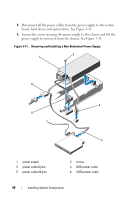
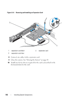
Installing a Non-Redundant Power Supply CAUTION: Many repairs may only be done by a certified service technician. You should only perform troubleshooting and simple repairs as authorized in your product documentation, or as directed by the online or telephone service and support team. Damage due to servicing that is not authorized by Dell is not covered by your warranty. Read and follow the safety instructions that came with the product. 1 Turn off the system, including any attached peripherals, and disconnect the system from its electrical outlet. 1 Open the system. See "Opening the System" on page 82. 2 Place the power supply on the chassis. See Figure 3-11. Tighten the screw to secure the power supply to the chassis. 3 Connect all the power cables to the system board, hard drive(s), and optical drive. 4 Replace the system cover. See "Closing the System" on page 83. 5 Connect the power cable to the power supply and plug the cable into a power outlet. Expansion Card and Expansion-Card Riser Expansion Card Installation Guidelines Your system supports one x16 Gen2 PCIe expansion card installed in the slot 1 connector on the expansion-card riser. CAUTION: Expansion card can only be installed in the slots on the expansioncard riser. Do not attempt to install expansion cards directly into the riser connector on the system board. • The expansion slot supports full-height, half-length cards. • The expansion-card slot is not hot-swappable. • PCI Express Generation 2 expansion card is supported in the slot. CAUTION: To ensure proper cooling, only one of the two expansion cards can have a power consumption of greater than 15 W (up to 25 W maximum), not including the integrated storage controller. Installing System Components 99
-
 1
1 -
2
-
3
-
4
-
5
-
6
-
7
-
8
-
9
-
10
-
11
-
12
-
13
-
14
-
15
-
16
-
17
-
18
-
19
-
20
-
21
-
22
-
23
-
24
-
25
-
26
-
27
-
28
-
29
-
30
-
31
-
32
-
33
-
34
-
35
-
36
-
37
-
38
-
39
-
40
-
41
-
42
-
43
-
44
-
45
-
46
-
47
-
48
-
49
-
50
-
51
-
52
-
53
-
54
-
55
-
56
-
57
-
58
-
59
-
60
-
61
-
62
-
63
-
64
-
65
-
66
-
67
-
68
-
69
-
70
-
71
-
72
-
73
-
74
-
75
-
76
-
77
-
78
-
79
-
80
-
81
-
82
-
83
-
84
-
85
-
86
-
87
-
88
-
89
-
90
-
91
-
92
-
93
-
 94
94 -
 95
95 -
 96
96 -
 97
97 -
 98
98 -
 99
99 -
 100
100 -
 101
101 -
 102
102 -
 103
103 -
 104
104 -
105
-
106
-
107
-
108
-
109
-
110
-
111
-
112
-
113
-
114
-
115
-
116
-
117
-
118
-
119
-
120
-
121
-
122
-
123
-
124
-
125
-
126
-
127
-
128
-
129
-
130
-
131
-
132
-
133
-
134
-
135
-
136
-
137
-
138
-
139
-
140
-
141
-
142
-
143
-
144
-
145
-
146
-
147
-
148
-
149
-
150
-
151
-
152
-
153
-
154
-
155
-
156
-
157
-
158
-
159
-
160
-
161
-
162
-
163
-
164
-
165
-
166
-
167
-
168
-
169
-
170
-
171
-
172
-
173
-
174
-
175
-
176
-
177
-
178
-
179
-
180
-
181
-
182
-
183
-
184
-
185
-
186
-
187
-
188
 |
 |
