Dell PowerEdge R415 Hardware Owner's Manual - Page 124
Installing Memory Modules, WARNING, CAUTION
 |
View all Dell PowerEdge R415 manuals
Add to My Manuals
Save this manual to your list of manuals |
Page 124 highlights
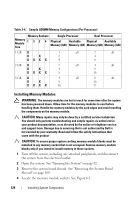
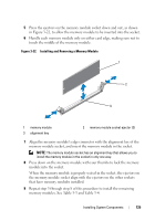
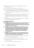
Table 3-4. Sample UDIMM Memory Configurations (Per Processor) Memory Sockets Single Processor Dual Processor Memory Module 1 Size 3 2 4 Physical Available Physical Available Memory (GB) Memory (GB) Memory (GB) Memory (GB) 1 GB X 1 all 2 all X X 2 4 XXX X 4 8 2 GB X 2 X X 4 XXX X 8 all 4 all 8 16 4 GB X 4 all 8 all X X 8 16 XXX X 16 32 Installing Memory Modules WARNING: The memory modules are hot to touch for some time after the system has been powered down. Allow time for the memory modules to cool before handling them. Handle the memory modules by the card edges and avoid touching the components on the memory module. CAUTION: Many repairs may only be done by a certified service technician. You should only perform troubleshooting and simple repairs as authorized in your product documentation, or as directed by the online or telephone service and support team. Damage due to servicing that is not authorized by Dell is not covered by your warranty. Read and follow the safety instructions that came with the product CAUTION: To ensure proper system cooling, memory-module blanks must be installed in any memory socket that is not occupied. Remove memory-module blanks only if you intend to install memory in those sockets. 1 Turn off the system, including any attached peripherals, and disconnect the system from the electrical outlet. 2 Open the system. See "Opening the System" on page 82. 3 Remove the system board shroud. See "Removing the System Board Shroud" on page 109. 4 Locate the memory module sockets. See Figure 6-1. 124 Installing System Components
-
 1
1 -
2
-
3
-
4
-
5
-
6
-
7
-
8
-
9
-
10
-
11
-
12
-
13
-
14
-
15
-
16
-
17
-
18
-
19
-
20
-
21
-
22
-
23
-
24
-
25
-
26
-
27
-
28
-
29
-
30
-
31
-
32
-
33
-
34
-
35
-
36
-
37
-
38
-
39
-
40
-
41
-
42
-
43
-
44
-
45
-
46
-
47
-
48
-
49
-
50
-
51
-
52
-
53
-
54
-
55
-
56
-
57
-
58
-
59
-
60
-
61
-
62
-
63
-
64
-
65
-
66
-
67
-
68
-
69
-
70
-
71
-
72
-
73
-
74
-
75
-
76
-
77
-
78
-
79
-
80
-
81
-
82
-
83
-
84
-
85
-
86
-
87
-
88
-
89
-
90
-
91
-
92
-
93
-
94
-
95
-
96
-
97
-
98
-
99
-
100
-
101
-
102
-
103
-
104
-
105
-
106
-
107
-
108
-
109
-
110
-
111
-
112
-
113
-
114
-
115
-
116
-
117
-
118
-
 119
119 -
 120
120 -
 121
121 -
 122
122 -
 123
123 -
 124
124 -
 125
125 -
 126
126 -
 127
127 -
 128
128 -
 129
129 -
130
-
131
-
132
-
133
-
134
-
135
-
136
-
137
-
138
-
139
-
140
-
141
-
142
-
143
-
144
-
145
-
146
-
147
-
148
-
149
-
150
-
151
-
152
-
153
-
154
-
155
-
156
-
157
-
158
-
159
-
160
-
161
-
162
-
163
-
164
-
165
-
166
-
167
-
168
-
169
-
170
-
171
-
172
-
173
-
174
-
175
-
176
-
177
-
178
-
179
-
180
-
181
-
182
-
183
-
184
-
185
-
186
-
187
-
188
 |
 |
