Dell PowerEdge R415 Hardware Owner's Manual - Page 147
See Installing the Integrated Storage Controller Card on See
 |
View all Dell PowerEdge R415 manuals
Add to My Manuals
Save this manual to your list of manuals |
Page 147 highlights
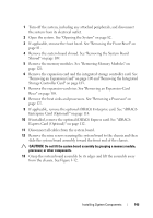
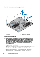
4 Replace all the memory modules. See "Removing Memory Modules" on page 126 and "Installing Memory Modules" on page 124. 5 Holding the system board by its edges, lower it into the chassis. CAUTION: Do not lift the system board assembly by grasping a memory module, processor, or other components. 6 Slightly lift up the front of the system board and maneuver it to the bottom of the chassis until it lays completely flat. 7 Push the system board toward the back of the chassis until the board is in place. 8 Tighten the nine screws that secure the system board to the chassis. See Figure 3-32. 9 Replace the heat sinks and tighten the processor heat sink screws. See "Installing a Processor" on page 130. 10 Connect the cables in the order listed below (see Figure 6-1 for the locations of the connectors on the system board): • SATA interface cable, if applicable • Control panel interface cable connector • Optical drive power cable connector • Control panel USB interface cable connector • SAS backplane power cable connector • System board power cable connectors 11 Replace the expansion-card risers. See "Replacing an Expansion-Card Riser" on page 107. 12 If applicable, install the expansion card. See "Installing an Expansion Card" on page 101. 13 If applicable, re-install the integrated storage controller card. See "Installing the Integrated Storage Controller Card" on page 104. After connecting the SAS cables to the controller, make sure to place the cables under the guide on the end of riser 1. Installing System Components 147
-
 1
1 -
2
-
3
-
4
-
5
-
6
-
7
-
8
-
9
-
10
-
11
-
12
-
13
-
14
-
15
-
16
-
17
-
18
-
19
-
20
-
21
-
22
-
23
-
24
-
25
-
26
-
27
-
28
-
29
-
30
-
31
-
32
-
33
-
34
-
35
-
36
-
37
-
38
-
39
-
40
-
41
-
42
-
43
-
44
-
45
-
46
-
47
-
48
-
49
-
50
-
51
-
52
-
53
-
54
-
55
-
56
-
57
-
58
-
59
-
60
-
61
-
62
-
63
-
64
-
65
-
66
-
67
-
68
-
69
-
70
-
71
-
72
-
73
-
74
-
75
-
76
-
77
-
78
-
79
-
80
-
81
-
82
-
83
-
84
-
85
-
86
-
87
-
88
-
89
-
90
-
91
-
92
-
93
-
94
-
95
-
96
-
97
-
98
-
99
-
100
-
101
-
102
-
103
-
104
-
105
-
106
-
107
-
108
-
109
-
110
-
111
-
112
-
113
-
114
-
115
-
116
-
117
-
118
-
119
-
120
-
121
-
122
-
123
-
124
-
125
-
126
-
127
-
128
-
129
-
130
-
131
-
132
-
133
-
134
-
135
-
136
-
137
-
138
-
139
-
140
-
141
-
 142
142 -
 143
143 -
 144
144 -
 145
145 -
 146
146 -
 147
147 -
 148
148 -
 149
149 -
 150
150 -
 151
151 -
 152
152 -
153
-
154
-
155
-
156
-
157
-
158
-
159
-
160
-
161
-
162
-
163
-
164
-
165
-
166
-
167
-
168
-
169
-
170
-
171
-
172
-
173
-
174
-
175
-
176
-
177
-
178
-
179
-
180
-
181
-
182
-
183
-
184
-
185
-
186
-
187
-
188
 |
 |
