Dell PowerEdge R415 Hardware Owner's Manual - Page 107
Replacing an Expansion-Card Riser, Internal USB Memory Key - dimensions
 |
View all Dell PowerEdge R415 manuals
Add to My Manuals
Save this manual to your list of manuals |
Page 107 highlights
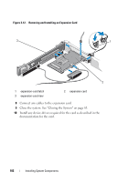
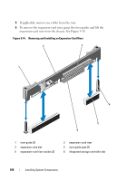
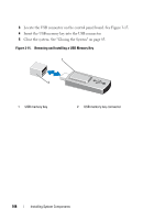
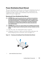
Replacing an Expansion-Card Riser 1 To install an expansion-card riser, align the riser guides with the riser guide posts on the system board. See Figure 3-14. 2 Lower the expansion-card riser into place until the expansion-card riser connector is fully seated. 3 If applicable, reinstall the integrated storage controller card. See "Installing the Integrated Storage Controller Card" on page 104. 4 If applicable, reinstall the expansion card. See "Installing an Expansion Card" on page 101. 5 If required, connect any cables to the riser. 6 Close the system. See "Closing the System" on page 83. Internal USB Memory Key The USB memory key can be used as a boot device, security key, or mass storage device. To use the internal USB connector, the Internal USB Port option must be enabled in the Integrated Devices screen of the System Setup program. To boot from the USB memory key, you must configure the USB memory key with a boot image and then specify the USB memory key in the boot sequence in the System Setup program. See "Boot Settings Screen" on page 63. For information on creating a bootable file on the USB memory key, see the user documentation that accompanied the USB memory key. CAUTION: Many repairs may only be done by a certified service technician. You should only perform troubleshooting and simple repairs as authorized in your product documentation, or as directed by the online or telephone service and support team. Damage due to servicing that is not authorized by Dell is not covered by your warranty. Read and follow the safety instructions that came with the product. NOTE: To avoid interference with other components, the maximum allowable dimensions of the USB key are 24 mm (.94 in) wide x 79 mm (3.11 in) long x 8.6 mm (.33 in) high. 1 Turn off the system, including any attached peripherals, and disconnect the system from the electrical outlet. 2 Open the system. See "Opening the System" on page 82. Installing System Components 107
-
 1
1 -
2
-
3
-
4
-
5
-
6
-
7
-
8
-
9
-
10
-
11
-
12
-
13
-
14
-
15
-
16
-
17
-
18
-
19
-
20
-
21
-
22
-
23
-
24
-
25
-
26
-
27
-
28
-
29
-
30
-
31
-
32
-
33
-
34
-
35
-
36
-
37
-
38
-
39
-
40
-
41
-
42
-
43
-
44
-
45
-
46
-
47
-
48
-
49
-
50
-
51
-
52
-
53
-
54
-
55
-
56
-
57
-
58
-
59
-
60
-
61
-
62
-
63
-
64
-
65
-
66
-
67
-
68
-
69
-
70
-
71
-
72
-
73
-
74
-
75
-
76
-
77
-
78
-
79
-
80
-
81
-
82
-
83
-
84
-
85
-
86
-
87
-
88
-
89
-
90
-
91
-
92
-
93
-
94
-
95
-
96
-
97
-
98
-
99
-
100
-
101
-
 102
102 -
 103
103 -
 104
104 -
 105
105 -
 106
106 -
 107
107 -
 108
108 -
 109
109 -
 110
110 -
 111
111 -
 112
112 -
113
-
114
-
115
-
116
-
117
-
118
-
119
-
120
-
121
-
122
-
123
-
124
-
125
-
126
-
127
-
128
-
129
-
130
-
131
-
132
-
133
-
134
-
135
-
136
-
137
-
138
-
139
-
140
-
141
-
142
-
143
-
144
-
145
-
146
-
147
-
148
-
149
-
150
-
151
-
152
-
153
-
154
-
155
-
156
-
157
-
158
-
159
-
160
-
161
-
162
-
163
-
164
-
165
-
166
-
167
-
168
-
169
-
170
-
171
-
172
-
173
-
174
-
175
-
176
-
177
-
178
-
179
-
180
-
181
-
182
-
183
-
184
-
185
-
186
-
187
-
188
 |
 |
