Denon AVR-5805MK2 Owners Manual - Page 10
Connecting Audio Components
 |
UPC - 081757507400
View all Denon AVR-5805MK2 manuals
Add to My Manuals
Save this manual to your list of manuals |
Page 10 highlights
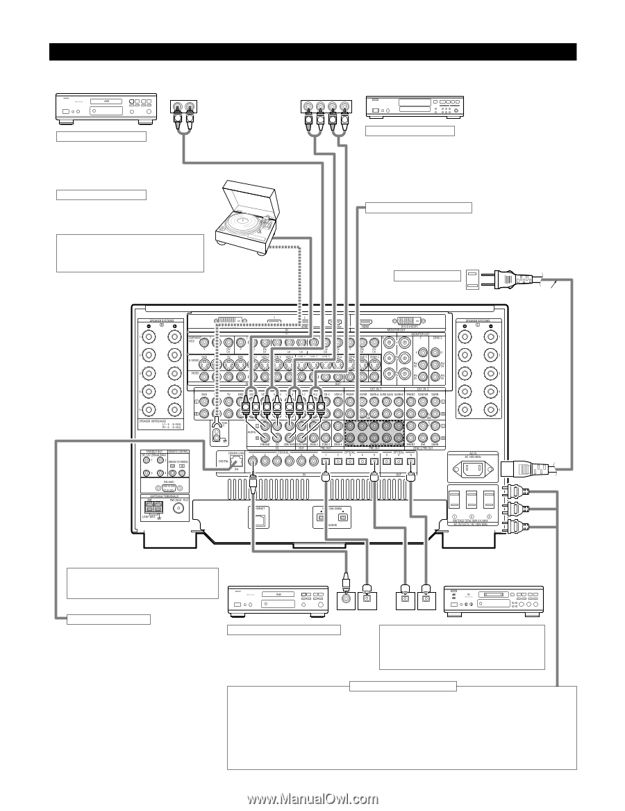
Connecting Audio Components • When making connections, also refer to the operating instructions of the other components. CD player DIGITAL AUDIO OUTPUT RL OUTPUT INPUT R LRL CD recorder or Tape deck B RL Connecting a CD player Connect the CD player's analog output jacks (ANALOG OUTPUT) to this unit's CD jacks using pin plug cords. Connecting a turntable Connect the turntable's output cord to the AVR-5805's PHONO jacks, the L (left) plug to the L jack, the R (right) plug to the right jack. NOTE: This unit cannot be used with MC cartridges directly. Use a separate head amplifier or step-up transformer. Turntable (MM cartridge) If humming or other noise is generated when the ground wire is connected, disconnect the ground wire. Ground wire RLRL Connecting a tape deck Connections for recording: Connect the tape deck's recording input jacks (LINE IN or REC) to this unit's tape recording (OUT) jacks using pin plug cords. Connections for playback: Connect the tape deck's playback output jacks (LINE OUT or PB) to this unit's tape playback (IN) jacks using pin plug cords. Connecting the pre-out jacks Use these jacks if you wish to connect external power amplifier(s) to increase the power of the front, center, surround and surround back sound channels, or for connection to powered loudspeakers. When using only one surround back speaker, connect it to left channel. AC outlets (wall) AC 120V, 60Hz AC cord (Supplied) RL RL LR LR Route the connection cords, etc., in such a way that they do not obstruct the ventilation holes. DENON Link terminal Use this terminal to connect a DENON DVD player for high quality digital multichannel sound. (See page 18) CD player or other component equipped with digital output jacks DIGITAL AUDIO COAXIAL OPTICAL OUTPUT MD recorder, CD recorder or other component equipped with digital input/output jacks B OUTPUT INPUT OPTICAL Connecting the DIGITAL jacks Use these for connections to audio equipment with digital output. Only one type of connector needs to be used, you can decide which based on availability of coaxial and optical inputs. Refer to pages 58, 59 for instructions on setting this terminal. NOTES: • Use 75 Ω/ohms cable pin cords for coaxial connections. • Use optical cables for optical connections, removing the cap before connecting. Connecting the AC OUTLETS AC OUTLETS • SWITCHED (total capacity - 120 W (1 A.)) The power to these outlets is turned on and off in conjunction with the POWER switch on the main unit, and when the power is switched between on and standby from the remote control unit. No power is supplied from these outlets when this unit's power is at standby. Never connect equipment whose total capacity is above 120 W (1 A.) NOTES: • Only use the AC OUTLETS for audio equipment. Never use them for hair driers, TVs or other electrical appliances. • The AC outlets can be set to turn on and off for the different functions. For details, see "Setting the AC Outlet Assign". (See pages 109, 110) 10
-
 1
1 -
2
-
3
-
4
-
 5
5 -
 6
6 -
 7
7 -
 8
8 -
 9
9 -
 10
10 -
 11
11 -
 12
12 -
 13
13 -
 14
14 -
 15
15 -
16
-
17
-
18
-
19
-
20
-
21
-
22
-
23
-
24
-
25
-
26
-
27
-
28
-
29
-
30
-
31
-
32
-
33
-
34
-
35
-
36
-
37
-
38
-
39
-
40
-
41
-
42
-
43
-
44
-
45
-
46
-
47
-
48
-
49
-
50
-
51
-
52
-
53
-
54
-
55
-
56
-
57
-
58
-
59
-
60
-
61
-
62
-
63
-
64
-
65
-
66
-
67
-
68
-
69
-
70
-
71
-
72
-
73
-
74
-
75
-
76
-
77
-
78
-
79
-
80
-
81
-
82
-
83
-
84
-
85
-
86
-
87
-
88
-
89
-
90
-
91
-
92
-
93
-
94
-
95
-
96
-
97
-
98
-
99
-
100
-
101
-
102
-
103
-
104
-
105
-
106
-
107
-
108
-
109
-
110
-
111
-
112
-
113
-
114
-
115
-
116
-
117
-
118
-
119
-
120
-
121
-
122
-
123
-
124
-
125
-
126
-
127
-
128
-
129
-
130
-
131
-
132
-
133
-
134
-
135
-
136
-
137
-
138
-
139
-
140
-
141
-
142
-
143
-
144
-
145
-
146
-
147
-
148
-
149
-
150
-
151
-
152
-
153
-
154
-
155
-
156
-
157
-
158
-
159
-
160
-
161
-
162
-
163
-
164
-
165
-
166
-
167
-
168
-
169
-
170
-
171
-
172
-
173
-
174
-
175
-
176
-
177
-
178
-
179
-
180
-
181
-
182
-
183
-
184
-
185
-
186
-
187
-
188
-
189
-
190
-
191
-
192
 |
 |