Denon AVR-5805MK2 Owners Manual - Page 36
Speaker system measurement
 |
UPC - 081757507400
View all Denon AVR-5805MK2 manuals
Add to My Manuals
Save this manual to your list of manuals |
Page 36 highlights
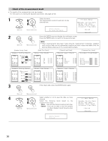
IV. Speaker system measurement • With these measurements, the "Speaker Configuration", "Delay Time", "Channel Level", "Crossover Frequency" and "Room EQ" are analyzed automatically. The main listening position is measured first, so leave the microphone where it is. 1 Select the "OK Start" and press the Cursor left button. Measurements for the first point start. (Main unit) CH SEL ENTER (Main unit) CH SEL ENTER Main Position OK Start (Remote control unit) (Remote control unit) NOTE: • With these measurements, test tones are not output from channels to which speakers have been judged not to be connected in the preliminary measurements. Do not change the connection of speakers or the subwoofer's volume after performing the preparation measurements and before performing these measurements. 2 q The screen shown at the right appears once the measurements for the main listening position are completed. Next the measurements for the second point will be taken. Place the microphone at the second listening position. For instructions on the position in which the microphone should be placed, see page 30. (When making the measurements, be sure to position the microphone at the approximate ear height of the seated listener(s).) w Select the "OK Next" and press the Cursor left button. Measurements for the second point start. (Main unit) CH SEL ENTER (Main unit) CH SEL ENTER (Remote control unit) (Remote control unit) 2nd Position OK Next 3 Perform step 2 repeatedly. The more measurement points, the better the resulting room correction effect. We recommend a minimum of 6 measurement points - 8 measurement points provides the best room correction effect. 36
-
 1
1 -
2
-
3
-
4
-
5
-
6
-
7
-
8
-
9
-
10
-
11
-
12
-
13
-
14
-
15
-
16
-
17
-
18
-
19
-
20
-
21
-
22
-
23
-
24
-
25
-
26
-
27
-
28
-
29
-
30
-
 31
31 -
 32
32 -
 33
33 -
 34
34 -
 35
35 -
 36
36 -
 37
37 -
 38
38 -
 39
39 -
 40
40 -
 41
41 -
42
-
43
-
44
-
45
-
46
-
47
-
48
-
49
-
50
-
51
-
52
-
53
-
54
-
55
-
56
-
57
-
58
-
59
-
60
-
61
-
62
-
63
-
64
-
65
-
66
-
67
-
68
-
69
-
70
-
71
-
72
-
73
-
74
-
75
-
76
-
77
-
78
-
79
-
80
-
81
-
82
-
83
-
84
-
85
-
86
-
87
-
88
-
89
-
90
-
91
-
92
-
93
-
94
-
95
-
96
-
97
-
98
-
99
-
100
-
101
-
102
-
103
-
104
-
105
-
106
-
107
-
108
-
109
-
110
-
111
-
112
-
113
-
114
-
115
-
116
-
117
-
118
-
119
-
120
-
121
-
122
-
123
-
124
-
125
-
126
-
127
-
128
-
129
-
130
-
131
-
132
-
133
-
134
-
135
-
136
-
137
-
138
-
139
-
140
-
141
-
142
-
143
-
144
-
145
-
146
-
147
-
148
-
149
-
150
-
151
-
152
-
153
-
154
-
155
-
156
-
157
-
158
-
159
-
160
-
161
-
162
-
163
-
164
-
165
-
166
-
167
-
168
-
169
-
170
-
171
-
172
-
173
-
174
-
175
-
176
-
177
-
178
-
179
-
180
-
181
-
182
-
183
-
184
-
185
-
186
-
187
-
188
-
189
-
190
-
191
-
192
 |
 |
