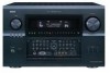
Denon AVR-5805MK2 Owners Manual - Page 17
Connecting the ZONE2 jacks
 |
UPC - 081757507400
View all Denon AVR-5805MK2 manuals
Add to My Manuals
Save this manual to your list of manuals |
Page 17 highlights
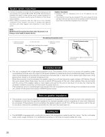
Connecting the ZONE2 jacks 2 ZONE2 preout CONNECTIONS • If another power amplifier or pre-main (integrated) amplifier is connected, the Zone2 preout (variable level) jacks can be used to play a different program source in Zone2 the same time. (See page 152) • The Zone2 video out is only use for the Zone2. • The connection diagram below is an example of multi-channel playback in Zone2. Please see page 154 when you would like to have 2-channel playback in Zone2. CONTROL terminal These terminals are used for an exteral controller. Perform the following operation before using an external controller connected to the RS-232C terminal: 1. Press the ON/STANDBY button on the main unit and set the unit to the operating mode. 2. Perform the operation to turn off the power from the external control. 3. Check that the product has been set to the standby mode. After checking the above, check the connections of the external controller. Operation is possible. Another room TV TRIGGER OUT Turn the DC 12V voltage on and off for the individual functions and surround modes. For details, see "Setting the Trigger Out". (See pages 107, 108) Power amplifier Extension jacks for future use. L RC-617 R INFRARED SENSOR R L OUTPUT INPUT For instructions on operations using the MULTI ZONE jacks, see pages 151~165. See pages 155, 156 for the connection method of Zone3 and Zone4. AUX OUT RC-616 INFRARED RETRANSMITTER Connecting a component with video and audio jacks to the V.AUX input jacks • To connect the video signal, connect using a 75 Ω/ohms video signal cable cord. Connecting a Video game component • Connect the Video game component's output jacks to this unit's V. AUX INPUT jacks. Connecting a video camera component • Connect the video camera component's output jacks to this unit's V. AUX INPUT jacks. LR Video game OUTPUT OPTICAL R L VIDEO OUT S-VIDEO OUT RL Video camera RL OUTPUT VIDEO OUT S-VIDEO OUT RL DIGITAL OUT LINE OUT VIDEO OUT S-VIDEO OUT LINE OUT VIDEO OUT S-VIDEO OUT 17
-
 1
1 -
2
-
3
-
4
-
5
-
6
-
7
-
8
-
9
-
10
-
11
-
 12
12 -
 13
13 -
 14
14 -
 15
15 -
 16
16 -
 17
17 -
 18
18 -
 19
19 -
 20
20 -
 21
21 -
 22
22 -
23
-
24
-
25
-
26
-
27
-
28
-
29
-
30
-
31
-
32
-
33
-
34
-
35
-
36
-
37
-
38
-
39
-
40
-
41
-
42
-
43
-
44
-
45
-
46
-
47
-
48
-
49
-
50
-
51
-
52
-
53
-
54
-
55
-
56
-
57
-
58
-
59
-
60
-
61
-
62
-
63
-
64
-
65
-
66
-
67
-
68
-
69
-
70
-
71
-
72
-
73
-
74
-
75
-
76
-
77
-
78
-
79
-
80
-
81
-
82
-
83
-
84
-
85
-
86
-
87
-
88
-
89
-
90
-
91
-
92
-
93
-
94
-
95
-
96
-
97
-
98
-
99
-
100
-
101
-
102
-
103
-
104
-
105
-
106
-
107
-
108
-
109
-
110
-
111
-
112
-
113
-
114
-
115
-
116
-
117
-
118
-
119
-
120
-
121
-
122
-
123
-
124
-
125
-
126
-
127
-
128
-
129
-
130
-
131
-
132
-
133
-
134
-
135
-
136
-
137
-
138
-
139
-
140
-
141
-
142
-
143
-
144
-
145
-
146
-
147
-
148
-
149
-
150
-
151
-
152
-
153
-
154
-
155
-
156
-
157
-
158
-
159
-
160
-
161
-
162
-
163
-
164
-
165
-
166
-
167
-
168
-
169
-
170
-
171
-
172
-
173
-
174
-
175
-
176
-
177
-
178
-
179
-
180
-
181
-
182
-
183
-
184
-
185
-
186
-
187
-
188
-
189
-
190
-
191
-
192
 |
 |
