Epson Stylus Pro WT7900 User's Guide - Page 31
short rod B into the plastic connectors.
 |
View all Epson Stylus Pro WT7900 manuals
Add to My Manuals
Save this manual to your list of manuals |
Page 31 highlights
Setting Up the Printer | 31 Note: Once inserted, the pins cannot be removed. 3. Insert the pins through the guides, pressing them into place. 4. Open one of the scissor arms as shown. Insert two long rods (A) and one short rod (B) into the plastic connectors. 31
-
 1
1 -
2
-
3
-
4
-
5
-
6
-
7
-
8
-
9
-
10
-
11
-
12
-
13
-
14
-
15
-
16
-
17
-
18
-
19
-
20
-
21
-
22
-
23
-
24
-
25
-
 26
26 -
 27
27 -
 28
28 -
 29
29 -
 30
30 -
 31
31 -
 32
32 -
 33
33 -
 34
34 -
 35
35 -
 36
36 -
37
-
38
-
39
-
40
-
41
-
42
-
43
-
44
-
45
-
46
-
47
-
48
-
49
-
50
-
51
-
52
-
53
-
54
-
55
-
56
-
57
-
58
-
59
-
60
-
61
-
62
-
63
-
64
-
65
-
66
-
67
-
68
-
69
-
70
-
71
-
72
-
73
-
74
-
75
-
76
-
77
-
78
-
79
-
80
-
81
-
82
-
83
-
84
-
85
-
86
-
87
-
88
-
89
-
90
-
91
-
92
-
93
-
94
-
95
-
96
-
97
-
98
-
99
-
100
-
101
-
102
-
103
-
104
-
105
-
106
-
107
-
108
-
109
-
110
-
111
-
112
-
113
-
114
-
115
-
116
-
117
-
118
-
119
-
120
-
121
-
122
-
123
-
124
-
125
-
126
-
127
-
128
-
129
-
130
-
131
-
132
-
133
-
134
-
135
-
136
 |
 |

31
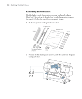
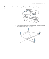
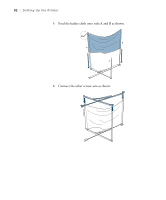
Setting Up the Printer
|
31
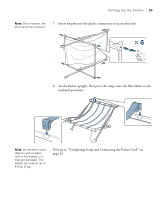
3.
Insert the pins through the guides, pressing them into place.
4.
Open one of the scissor arms as shown. Insert two long rods (A) and one
short rod (B) into the plastic connectors.
Note:
Once inserted, the
pins cannot be removed.