Fluke 744 Fluke 744 Users Manual - Page 22
Operating Features, Input and Output Jacks - user manual
 |
View all Fluke 744 manuals
Add to My Manuals
Save this manual to your list of manuals |
Page 22 highlights
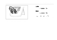
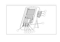
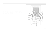
744 Users Manual Operating Features Input and Output Jacks Figure 5 shows the calibrator input and output jacks. Table 2 explains their use. Table 2. Input/Output Jacks and Connectors No. 1 2 3 4 5, 6 7, 8 9,10 Name Description Battery Eliminator jack w SERIAL PORT Jack for the Model BE9005 Battery Eliminator. Use the battery eliminator for bench-top applications where ac line power is available. This input does not charge the battery. Connects the calibrator to an RS-232 serial port on a personal computer. Pressure module connector TC input/output wMEAS V jacks wSOURCE mA, MEAS mA Ω RTD jacks wSOURCE V Ω RTD jacks Connects the calibrator to a pressure module. Jack for measuring or simulating thermocouples. This jack accepts a miniature polarized thermocouple plug with flat, in-line blades spaced 7.9 mm (0.312 in) center to center. Input jacks for measuring voltage, frequency, or three- or four-wire RTDs (Resistance Temperature Detectors). Jacks for sourcing or measuring current, measuring resistance and RTDs, and supplying loop power. Output jacks for sourcing voltage, resistance, frequency, and for simulating RTDs. 12
-
 1
1 -
2
-
3
-
4
-
5
-
6
-
7
-
8
-
9
-
10
-
11
-
12
-
13
-
14
-
15
-
16
-
 17
17 -
 18
18 -
 19
19 -
 20
20 -
 21
21 -
 22
22 -
 23
23 -
 24
24 -
 25
25 -
 26
26 -
 27
27 -
28
-
29
-
30
-
31
-
32
-
33
-
34
-
35
-
36
-
37
-
38
-
39
-
40
-
41
-
42
-
43
-
44
-
45
-
46
-
47
-
48
-
49
-
50
-
51
-
52
-
53
-
54
-
55
-
56
-
57
-
58
-
59
-
60
-
61
-
62
-
63
-
64
-
65
-
66
-
67
-
68
-
69
-
70
-
71
-
72
-
73
-
74
-
75
-
76
-
77
-
78
-
79
-
80
-
81
-
82
-
83
-
84
-
85
-
86
-
87
-
88
-
89
-
90
-
91
-
92
-
93
-
94
-
95
-
96
-
97
-
98
-
99
-
100
-
101
-
102
-
103
-
104
-
105
-
106
-
107
-
108
-
109
-
110
-
111
-
112
-
113
-
114
-
115
-
116
-
117
-
118
-
119
-
120
-
121
-
122
-
123
-
124
-
125
-
126
-
127
-
128
-
129
-
130
-
131
-
132
-
133
-
134
-
135
-
136
-
137
-
138
 |
 |