Fluke 744 Fluke 744 Users Manual - Page 65
Simulating Thermocouples, reference temperature accurately and enter
 |
View all Fluke 744 manuals
Add to My Manuals
Save this manual to your list of manuals |
Page 65 highlights
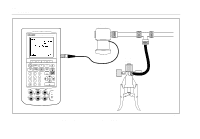
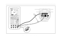
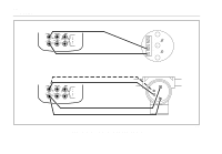
Simulating Thermocouples Note Refer to "Measuring Temperature" earlier in the manual for a table of data relating to thermocouple types supported by the calibrator. Connect the calibrator TC input/output to the instrument under test with thermocouple wire and the appropriate thermocouple mini-connector (polarized thermocouple plug with flat, in-line blades spaced 7.9 mm [0.312 in] center to center). One pin is wider than the other. Do not try to force a miniplug in the wrong polarization. Figure 20 shows this connection. Proceed as follows to simulate a thermocouple: 1. Attach the thermocouple leads to the appropriate TC miniplug, then to the TC input/output as Figure 13 shows. 2. If necessary, press M for SOURCE mode. 3. Press t for the display that prompts you to enter thermocouple type. 4. Press the u or d key followed by e to select the desired thermocouple type. Documenting Process Calibrator Using Source Mode 5. Press the u or d key followed by e to select Linear T (default), or Linear mV, (for calibrating a temperature transmitter that responds linearly to millivolt inputs). 6. Enter the temperature you want to simulate as prompted by the display and press e. Note If you use copper wire instead of thermocouple wire, the reference junction is no longer inside the calibrator. The reference junction is moved to the instrument (transmitter, indicator, controller, etc.) input terminals. You must measure this external reference temperature accurately and enter it into the calibrator. Do this by pressing s and setting Ref. Junc. Compensat and Ref. Junc. Temp. After you enter the external reference temperature, the calibrator corrects all voltages to compensate for this new reference junction temperature. 55
-
 1
1 -
2
-
3
-
4
-
5
-
6
-
7
-
8
-
9
-
10
-
11
-
12
-
13
-
14
-
15
-
16
-
17
-
18
-
19
-
20
-
21
-
22
-
23
-
24
-
25
-
26
-
27
-
28
-
29
-
30
-
31
-
32
-
33
-
34
-
35
-
36
-
37
-
38
-
39
-
40
-
41
-
42
-
43
-
44
-
45
-
46
-
47
-
48
-
49
-
50
-
51
-
52
-
53
-
54
-
55
-
56
-
57
-
58
-
59
-
 60
60 -
 61
61 -
 62
62 -
 63
63 -
 64
64 -
 65
65 -
 66
66 -
 67
67 -
 68
68 -
 69
69 -
 70
70 -
71
-
72
-
73
-
74
-
75
-
76
-
77
-
78
-
79
-
80
-
81
-
82
-
83
-
84
-
85
-
86
-
87
-
88
-
89
-
90
-
91
-
92
-
93
-
94
-
95
-
96
-
97
-
98
-
99
-
100
-
101
-
102
-
103
-
104
-
105
-
106
-
107
-
108
-
109
-
110
-
111
-
112
-
113
-
114
-
115
-
116
-
117
-
118
-
119
-
120
-
121
-
122
-
123
-
124
-
125
-
126
-
127
-
128
-
129
-
130
-
131
-
132
-
133
-
134
-
135
-
136
-
137
-
138
 |
 |