Fluke 744 Fluke 744 Users Manual - Page 63
Pressurize the pressure line with the pressure, source to the desired level as shown on
 |
View all Fluke 744 manuals
Add to My Manuals
Save this manual to your list of manuals |
Page 63 highlights
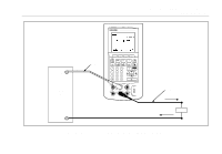
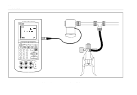
1. Connect a pressure module and pressure source to the calibrator as Figure 19 shows. The threads on the pressure modules accept ¼ NPT fittings. Use the supplied ¼ NPT to ¼ ISO adapter if necessary. 2. If necessary, press M for SOURCE mode. 3. Press p. The calibrator automatically senses which pressure module is attached and sets its range accordingly. 4. Zero the pressure module as described in the module's Instruction Sheet. Modules vary in zeroing procedures depending on module type. You MUST perform this step before you execute a task that sources or measures pressure. 5. Pressurize the pressure line with the pressure source to the desired level as shown on the display. 6. If desired, you can change pressure display units to psi, mHg, inHg, mH2O, inH2O, inH2O@60°F, ftH2O, bar, g/cm2, or Pa. Metric units (kPa, mmHg, etc.) are shown in Setup mode in their Documenting Process Calibrator Using Source Mode base units (Pa, mHg, etc.). Change the pressure display units as follows: a. Press s. b. Press Next Page twice. c. Press ewith the cursor on Pressure Units. d. Select the pressure units with the u or d keys. e. Press e. f. Press the Done softkey. 53
-
 1
1 -
2
-
3
-
4
-
5
-
6
-
7
-
8
-
9
-
10
-
11
-
12
-
13
-
14
-
15
-
16
-
17
-
18
-
19
-
20
-
21
-
22
-
23
-
24
-
25
-
26
-
27
-
28
-
29
-
30
-
31
-
32
-
33
-
34
-
35
-
36
-
37
-
38
-
39
-
40
-
41
-
42
-
43
-
44
-
45
-
46
-
47
-
48
-
49
-
50
-
51
-
52
-
53
-
54
-
55
-
56
-
57
-
 58
58 -
 59
59 -
 60
60 -
 61
61 -
 62
62 -
 63
63 -
 64
64 -
 65
65 -
 66
66 -
 67
67 -
 68
68 -
69
-
70
-
71
-
72
-
73
-
74
-
75
-
76
-
77
-
78
-
79
-
80
-
81
-
82
-
83
-
84
-
85
-
86
-
87
-
88
-
89
-
90
-
91
-
92
-
93
-
94
-
95
-
96
-
97
-
98
-
99
-
100
-
101
-
102
-
103
-
104
-
105
-
106
-
107
-
108
-
109
-
110
-
111
-
112
-
113
-
114
-
115
-
116
-
117
-
118
-
119
-
120
-
121
-
122
-
123
-
124
-
125
-
126
-
127
-
128
-
129
-
130
-
131
-
132
-
133
-
134
-
135
-
136
-
137
-
138
 |
 |