Fluke 744 Fluke 744 Users Manual - Page 66
Simulating RTDs, Temperature Detector
 |
View all Fluke 744 manuals
Add to My Manuals
Save this manual to your list of manuals |
Page 66 highlights
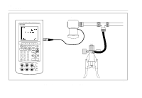
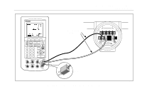
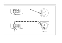
744 Users Manual Simulating RTDs Note Refer to Table 6 for information about RTD (Resistance-Temperature Detector) types supported by the calibrator. Connect the calibrator to the instrument under test as shown in Figure 21. The figure shows connections for two, three, or four-wire transmitters. For three or four-wire transmitters, use the 4-inch long stackable jumper cables to connect the third and fourth wires at the source V Ω RTD jacks. Proceed as follows to simulate an RTD (ResistanceTemperature Detector): 1. If necessary, press M for SOURCE mode. 2. Press t until the select RTD type display is showing. 3. Press the u or d keys followed by e to select the desired RTD type. 4. Enter the temperature you want to simulate as prompted by the display, then press e. 56
-
 1
1 -
2
-
3
-
4
-
5
-
6
-
7
-
8
-
9
-
10
-
11
-
12
-
13
-
14
-
15
-
16
-
17
-
18
-
19
-
20
-
21
-
22
-
23
-
24
-
25
-
26
-
27
-
28
-
29
-
30
-
31
-
32
-
33
-
34
-
35
-
36
-
37
-
38
-
39
-
40
-
41
-
42
-
43
-
44
-
45
-
46
-
47
-
48
-
49
-
50
-
51
-
52
-
53
-
54
-
55
-
56
-
57
-
58
-
59
-
60
-
 61
61 -
 62
62 -
 63
63 -
 64
64 -
 65
65 -
 66
66 -
 67
67 -
 68
68 -
 69
69 -
 70
70 -
 71
71 -
72
-
73
-
74
-
75
-
76
-
77
-
78
-
79
-
80
-
81
-
82
-
83
-
84
-
85
-
86
-
87
-
88
-
89
-
90
-
91
-
92
-
93
-
94
-
95
-
96
-
97
-
98
-
99
-
100
-
101
-
102
-
103
-
104
-
105
-
106
-
107
-
108
-
109
-
110
-
111
-
112
-
113
-
114
-
115
-
116
-
117
-
118
-
119
-
120
-
121
-
122
-
123
-
124
-
125
-
126
-
127
-
128
-
129
-
130
-
131
-
132
-
133
-
134
-
135
-
136
-
137
-
138
 |
 |