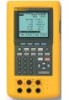
Fluke 744 Fluke 744 Users Manual - Page 87
for the pressure source function., to zero the pressure module.
 |
View all Fluke 744 manuals
Add to My Manuals
Save this manual to your list of manuals |
Page 87 highlights
The procedure for testing a pressure limit switch follows. The switch in this example sets at a high limit of 10 psi. The set state is a closed switch contact. For pressure switches, you use the Manual Test choice. For testing switches that do not require sourcing pressure, you can use the Auto Test choice. 1. Connect the test leads between the pressure switch contact output and the mA Ω RTD (middle) jacks on the calibrator. 2. Connect the pressure module to the calibrator, and connect a pressure line to the limit switch. Leave the pressure line vented to atmosphere. 3. If necessary, press M for MEASURE mode. 4. Press q q for the continuity measure function. 5. Press M for SOURCE mode. 6. Press p for the pressure source function. Documenting Process Calibrator Calibrating a Process Instrument 7. Press c to zero the pressure module. 8. Press M. 9. Press the As Found softkey. 10. Highlight 1 Pt. Switch Test from the menu and press e. 11. Press e to modify the parameters for Setpoint 1. 12. Make the following selections: Setpoint 1 = 10.000 psi Setpoint Type = High Set State = Short 13. Press the Done softkey. 14. Set the Tolerance to 0.5 psi. 15. The next parameters, Deadband Min and Deadband Max, are optional. Do not set them in this example. 77
-
 1
1 -
2
-
3
-
4
-
5
-
6
-
7
-
8
-
9
-
10
-
11
-
12
-
13
-
14
-
15
-
16
-
17
-
18
-
19
-
20
-
21
-
22
-
23
-
24
-
25
-
26
-
27
-
28
-
29
-
30
-
31
-
32
-
33
-
34
-
35
-
36
-
37
-
38
-
39
-
40
-
41
-
42
-
43
-
44
-
45
-
46
-
47
-
48
-
49
-
50
-
51
-
52
-
53
-
54
-
55
-
56
-
57
-
58
-
59
-
60
-
61
-
62
-
63
-
64
-
65
-
66
-
67
-
68
-
69
-
70
-
71
-
72
-
73
-
74
-
75
-
76
-
77
-
78
-
79
-
80
-
81
-
 82
82 -
 83
83 -
 84
84 -
 85
85 -
 86
86 -
 87
87 -
 88
88 -
 89
89 -
 90
90 -
 91
91 -
 92
92 -
93
-
94
-
95
-
96
-
97
-
98
-
99
-
100
-
101
-
102
-
103
-
104
-
105
-
106
-
107
-
108
-
109
-
110
-
111
-
112
-
113
-
114
-
115
-
116
-
117
-
118
-
119
-
120
-
121
-
122
-
123
-
124
-
125
-
126
-
127
-
128
-
129
-
130
-
131
-
132
-
133
-
134
-
135
-
136
-
137
-
138
 |
 |