Fluke 744 Fluke 744 Users Manual - Page 47
Using Resistance-Temperature Detectors (RTDs), RTD measurement inputs in two-, three-, or four-wire - 3 wire rtd
 |
View all Fluke 744 manuals
Add to My Manuals
Save this manual to your list of manuals |
Page 47 highlights
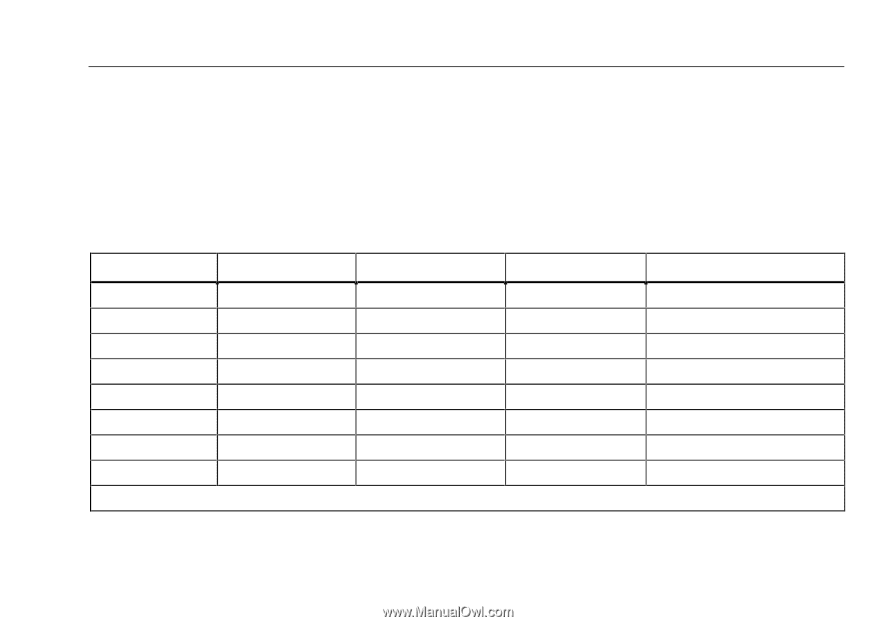
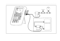
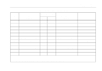
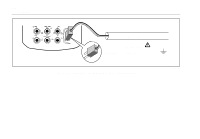
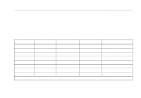
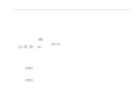
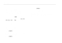
Documenting Process Calibrator Using Measure Mode Using Resistance-Temperature Detectors (RTDs) The calibrator accepts RTD types shown in Table 6. RTDs are characterized by their resistance at 0 °C (32 °F), which is called the "ice point" or R0. The most common R0 is 100 Ω. Most RTDs come in a three-terminal configuration. The calibrator accepts RTD measurement inputs in two-, three-, or four-wire connections as shown in Figure 15. A four-wire configuration provides the highest measurement precision, and two-wire provides the lowest measurement precision. Table 6. RTD Types Accepted RTD Type Ice Point (R ) 0 Pt100 (3926) 100 Ω *Pt100 (385) 100 Ω Ni120 (672) 120 Ω Pt200 (385) 200 Ω Pt500 (385) 500 Ω Pt1000 (385) 1000 Ω Cu10 (427) 9.035 Ω ** Pt100 (3916) 100 Ω *Per IEC 751-Standard **10 Ω @ 25 °C Material Platinum Platinum Nickel Platinum Platinum Platinum Copper Platinum α 0.003926 Ω/°C 0.00385 Ω/°C 0.00672 Ω/°C 0.00385 Ω/°C 0.00385 Ω/°C 0.00385 Ω/°C 0.00427 Ω/°C 0.003916 Ω/°C Range (°C) -200 to 630 -200 to 800 -80 to 260 -200 to 630 -200 to 630 -200 to 630 -100 to 260 -200 to 630 37
-
 1
1 -
2
-
3
-
4
-
5
-
6
-
7
-
8
-
9
-
10
-
11
-
12
-
13
-
14
-
15
-
16
-
17
-
18
-
19
-
20
-
21
-
22
-
23
-
24
-
25
-
26
-
27
-
28
-
29
-
30
-
31
-
32
-
33
-
34
-
35
-
36
-
37
-
38
-
39
-
40
-
41
-
 42
42 -
 43
43 -
 44
44 -
 45
45 -
 46
46 -
 47
47 -
 48
48 -
 49
49 -
 50
50 -
 51
51 -
 52
52 -
53
-
54
-
55
-
56
-
57
-
58
-
59
-
60
-
61
-
62
-
63
-
64
-
65
-
66
-
67
-
68
-
69
-
70
-
71
-
72
-
73
-
74
-
75
-
76
-
77
-
78
-
79
-
80
-
81
-
82
-
83
-
84
-
85
-
86
-
87
-
88
-
89
-
90
-
91
-
92
-
93
-
94
-
95
-
96
-
97
-
98
-
99
-
100
-
101
-
102
-
103
-
104
-
105
-
106
-
107
-
108
-
109
-
110
-
111
-
112
-
113
-
114
-
115
-
116
-
117
-
118
-
119
-
120
-
121
-
122
-
123
-
124
-
125
-
126
-
127
-
128
-
129
-
130
-
131
-
132
-
133
-
134
-
135
-
136
-
137
-
138
 |
 |