Motorola WA840GP User Guide - Page 21
Mounting Template appears., Print - install
 |
UPC - 612572118740
View all Motorola WA840GP manuals
Add to My Manuals
Save this manual to your list of manuals |
Page 21 highlights
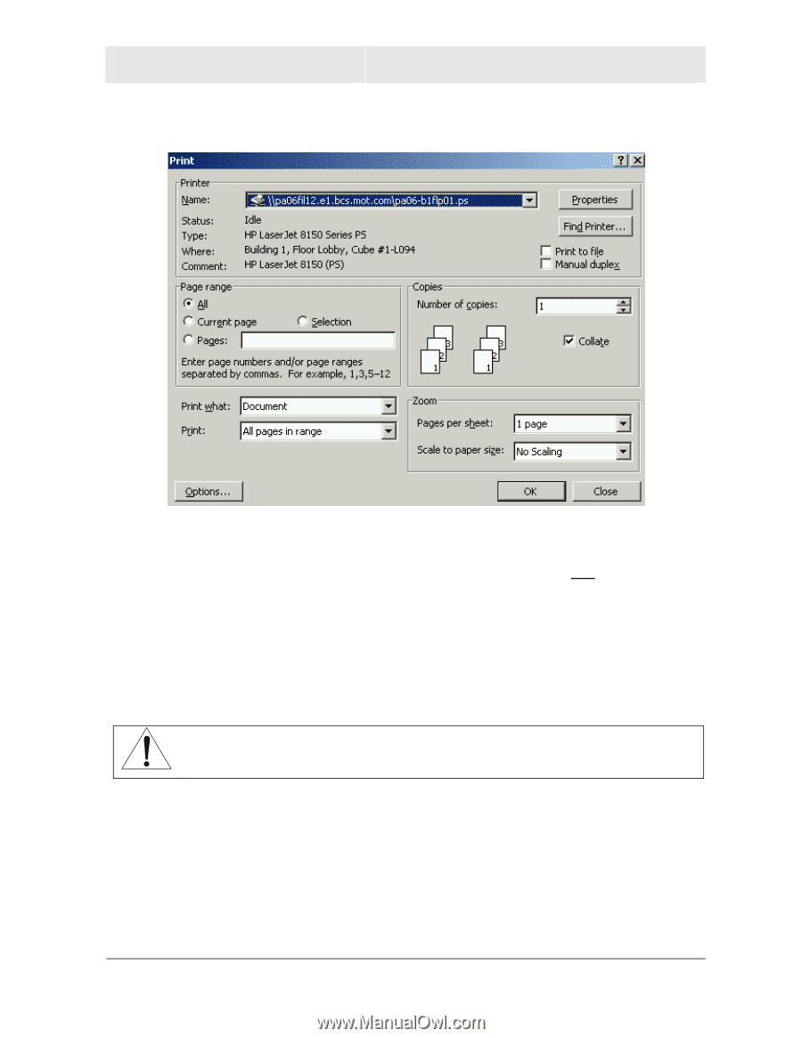
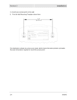
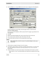
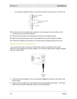
Installation Section 2 2 Click the Print icon or choose Print from the File menu to display the Print dialog box. In both the Pages from and to fields, enter the page number on which the Wall Mounting Template appears. Be sure you print the template at 100% scale and that Fit to page is not checked in the Print dialog box. 3 Click OK. 4 Measure the printed template with a ruler to ensure that it is the correct size. 5 Use a center punch to mark the center of the holes on the wall. 6 On the wall, locate the marks for the mounting holes you just made. WARNING! Before drilling holes, check the structure for potential damage to water, gas, or electric lines. 7 Drill the holes to a depth of at least 3.8 cm (1½ inches). 8 If necessary, seat an anchor in each hole. Use M5 x 38 mm (#10-16 x 1½ inch) screws with a flat underside and maximum screw head diameter of 10.5 mm to mount the access point. 9 Using a screwdriver, turn each screw until part of it protrudes from the wall, as shown: - There must be 4.0 mm (.16 inches) between the wall and the underside of the screw head. WA840 2-5
-
 1
1 -
2
-
3
-
4
-
5
-
6
-
7
-
8
-
9
-
10
-
11
-
12
-
13
-
14
-
15
-
 16
16 -
 17
17 -
 18
18 -
 19
19 -
 20
20 -
 21
21 -
 22
22 -
 23
23 -
 24
24 -
 25
25 -
 26
26 -
27
-
28
-
29
-
30
-
31
-
32
-
33
-
34
-
35
-
36
-
37
-
38
-
39
-
40
-
41
-
42
-
43
-
44
-
45
-
46
-
47
-
48
-
49
-
50
-
51
-
52
-
53
-
54
-
55
-
56
-
57
-
58
-
59
-
60
-
61
-
62
-
63
-
64
-
65
-
66
-
67
-
68
-
69
-
70
-
71
-
72
-
73
-
74
-
75
-
76
-
77
-
78
-
79
-
80
-
81
-
82
-
83
-
84
-
85
-
86
-
87
-
88
-
89
-
90
-
91
-
92
-
93
-
94
-
95
-
96
-
97
-
98
-
99
-
100
-
101
-
102
-
103
-
104
-
105
-
106
-
107
-
108
-
109
-
110
-
111
-
112
-
113
-
114
-
115
-
116
-
117
-
118
-
119
-
120
-
121
-
122
-
123
-
124
 |
 |