Motorola WA840GP User Guide - Page 22
Electrical Connection to Access Point, Power
 |
UPC - 612572118740
View all Motorola WA840GP manuals
Add to My Manuals
Save this manual to your list of manuals |
Page 22 highlights
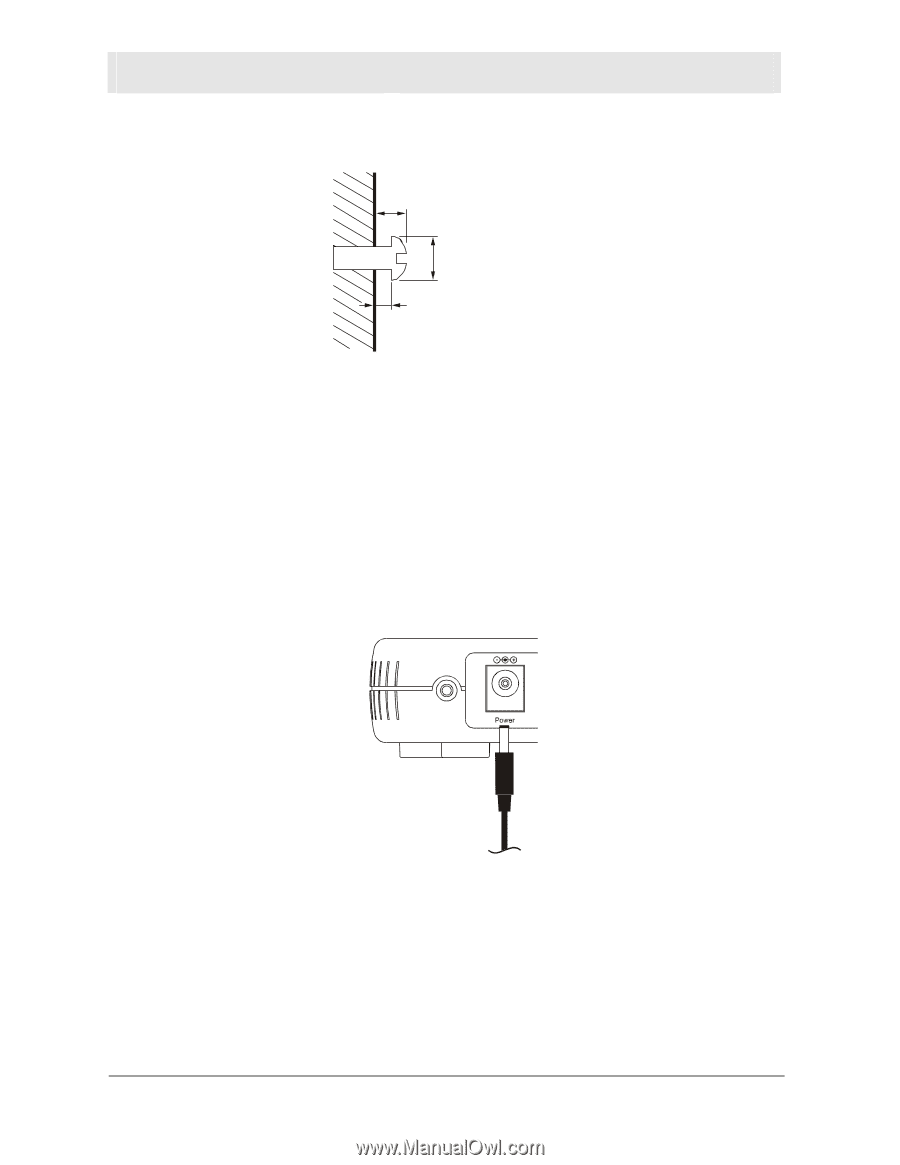
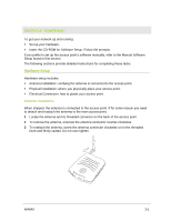
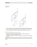
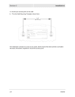
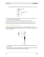
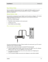
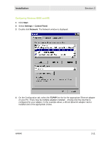
Section 2 Installation - The maximum distance from the wall to the top of the screw head is 7.6 mm (.3 in). 7.6 mm (.3 inches) maximum 10.5 mm (.4 inches) maximum 4.0 mm 10 Remove the front two plastic feet, nearest to the LED panel, from the bottom of the access point to uncover the keyholes. 11 Place the access point so the keyholes are above the mounting screws. 12 Slide the access point down until it stops against the top of the keyhole opening. 13 Follow the installation procedures for connecting and configuring the access point. Electrical Connection to Access Point Your access point does not have an On/Off power switch and therefore will only be powered on by plugging in the power adapter. Use only the original power adapter supplied with your access point. To power supply 1 Connect the power adapter to the access point's Power port, found on the back of the access point. 2 Plug the power adapter into a grounded and surge-protected power outlet. The Power LED on the front panel lights green when connected properly. 2-6 WA840
-
 1
1 -
2
-
3
-
4
-
5
-
6
-
7
-
8
-
9
-
10
-
11
-
12
-
13
-
14
-
15
-
16
-
 17
17 -
 18
18 -
 19
19 -
 20
20 -
 21
21 -
 22
22 -
 23
23 -
 24
24 -
 25
25 -
 26
26 -
 27
27 -
28
-
29
-
30
-
31
-
32
-
33
-
34
-
35
-
36
-
37
-
38
-
39
-
40
-
41
-
42
-
43
-
44
-
45
-
46
-
47
-
48
-
49
-
50
-
51
-
52
-
53
-
54
-
55
-
56
-
57
-
58
-
59
-
60
-
61
-
62
-
63
-
64
-
65
-
66
-
67
-
68
-
69
-
70
-
71
-
72
-
73
-
74
-
75
-
76
-
77
-
78
-
79
-
80
-
81
-
82
-
83
-
84
-
85
-
86
-
87
-
88
-
89
-
90
-
91
-
92
-
93
-
94
-
95
-
96
-
97
-
98
-
99
-
100
-
101
-
102
-
103
-
104
-
105
-
106
-
107
-
108
-
109
-
110
-
111
-
112
-
113
-
114
-
115
-
116
-
117
-
118
-
119
-
120
-
121
-
122
-
123
-
124
 |
 |