Panasonic HVX200A Operating Instructions - Page 78
Connecting external units continued
 |
UPC - 791871303351
View all Panasonic HVX200A manuals
Add to My Manuals
Save this manual to your list of manuals |
Page 78 highlights
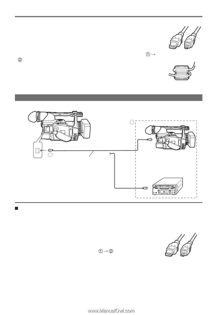
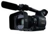
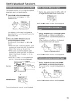
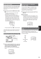
Connecting external units (continued) • Before proceeding to connect or disconnect 1394 cable, be absolutely sure to turn off the power of the units. • Before proceeding to connect the unit which uses a 6-pin type 1394 connector, carefully check the shape of the 1394 cable and the connectors on the 1394 cable. Connecting a connector upside down may damage the parts inside the unit and cause malfunctioning. Furthermore, connect the 1394 cable to the unit which uses a 6-pin type 1394 connector first. ( ĺ ). The above also applies to USB cable as well. 6-pin 4-pin type type • Do not apply force when connecting 1394 cable to 1394 connector as this may damage the connector. • When connecting to a PC, attach the ferrite core (provided) to the 1394 cable in such a way that the whole ferrite core fits within about 5 cm from the PC's connectors. Ferrite core (provided) Digital video equipment (Dubbing) This camera Other Digital video equipment 1 1394 2 1394 cable (optional) 4-pin type You can connect a digital video unit equipped with a DV connector and digitally transfer video and audio signals as well as time code. • Before proceeding to connect or disconnect 1394 cable, be absolutely sure to turn off the power of the units. • Before proceeding to connect the unit which uses a 6-pin type 1394 connector, carefully check the shape of the 1394 cable and the connectors on the 1394 cable. Connecting a connector upside down may damage the parts inside the unit and cause malfunctioning. Furthermore, connect the 1394 cable to the unit which uses a 6-pin type 1394 connector first. ( ĺ ) • When recording signals from an external unit, first check that video signals are supplied. • While signals from an external unit are being recorded, do not stop output on 6-pin 4-pin type type the external unit side or disconnect any of cables. This may lead to a failure to recognize the signals when you do recording again. • Do not apply force when connecting 1394 cable to 1394 connector as this may damage the connector. • No guarantees are made for the playback images when signals from an external device are recorded. (Video check level) 78
-
 1
1 -
2
-
3
-
4
-
5
-
6
-
7
-
8
-
9
-
10
-
11
-
12
-
13
-
14
-
15
-
16
-
17
-
18
-
19
-
20
-
21
-
22
-
23
-
24
-
25
-
26
-
27
-
28
-
29
-
30
-
31
-
32
-
33
-
34
-
35
-
36
-
37
-
38
-
39
-
40
-
41
-
42
-
43
-
44
-
45
-
46
-
47
-
48
-
49
-
50
-
51
-
52
-
53
-
54
-
55
-
56
-
57
-
58
-
59
-
60
-
61
-
62
-
63
-
64
-
65
-
66
-
67
-
68
-
69
-
70
-
71
-
72
-
 73
73 -
 74
74 -
 75
75 -
 76
76 -
 77
77 -
 78
78 -
 79
79 -
 80
80 -
 81
81 -
 82
82 -
 83
83 -
84
-
85
-
86
-
87
-
88
-
89
-
90
-
91
-
92
-
93
-
94
-
95
-
96
-
97
-
98
-
99
-
100
-
101
-
102
-
103
-
104
-
105
-
106
-
107
-
108
-
109
-
110
-
111
-
112
-
113
-
114
-
115
-
116
-
117
-
118
-
119
-
120
-
121
-
122
-
123
-
124
-
125
-
126
-
127
-
128
-
129
-
130
-
131
-
132
-
133
-
134
 |
 |