Ricoh FW780 Service Manual
Ricoh FW780 Manual
 |
View all Ricoh FW780 manuals
Add to My Manuals
Save this manual to your list of manuals |
Ricoh FW780 manual content summary:
- Ricoh FW780 | Service Manual - Page 1
RICOH GROUP COMPANIES A163/A251/A252 B047/B048 SERVICE MANUAL 001317MIU - Ricoh FW780 | Service Manual - Page 2
- Ricoh FW780 | Service Manual - Page 3
® ® RICOH GROUP COMPANIES A163/A251/A252/B047/B048 SERVICE MANUAL - Ricoh FW780 | Service Manual - Page 4
- Ricoh FW780 | Service Manual - Page 5
A163 SERVICE MANUAL 001317MIU - Ricoh FW780 | Service Manual - Page 6
- Ricoh FW780 | Service Manual - Page 7
Corporation and its member companies. NO PART OF THIS DOCUMENT MAY BE REPRODUCED IN ANY FASHION AND DISTRIBUTED WITHOUT THE PRIOR PERMISSION OF RICOH CORPORATION. All product names, domain names or product illustrations, including desktop images, used in this document are trademarks, registered - Ricoh FW780 | Service Manual - Page 8
- Ricoh FW780 | Service Manual - Page 9
WARNING The Service Manual contains information regarding service techniques, procedures, processes and spare parts of office equipment distributed by Ricoh Corporation. Users of this manual should be either service trained or certified by successfully completing a Ricoh Technical Training Program. - Ricoh FW780 | Service Manual - Page 10
- Ricoh FW780 | Service Manual - Page 11
LEGEND PRODUCT CODE A163 A251 A252 B047 B048 GESTETNER N/A N/A N/A A040 A041 COMPANY RICOH FW740 FW750 FW760 FW770 FW780 SAVIN N/A N/A N/A 7700W 7800W DOCUMENTATION HISTORY REV. NO. * 1 2 3 4 DATE 5/95 5/96 6/98 8/2001 COMMENTS Original Printing Revised Pages Reprint A251/A252 Addition B047/ - Ricoh FW780 | Service Manual - Page 12
- Ricoh FW780 | Service Manual - Page 13
check has to be made with exterior covers off or open while the main switch is turned on, keep hands away from electrified or mechanically driven components. 5. The inside and the metal parts of the fusing unit become extremely hot while the copier is operating. Be careful to avoid touching - Ricoh FW780 | Service Manual - Page 14
Do not incinerate the toner cartridge or the used toner. Toner dust may ignite suddenly when exposed to open flame. 2. Dispose of used toner, developer, and organic photoconductors according to local regulations. (These are non-toxic supplies.) 3. Dispose of replaced parts in accordance with local - Ricoh FW780 | Service Manual - Page 15
. 06/2004 OVERALL MACHINE INFORMATION 1. SPECIFICATIONS 1-1 2. PAPER PATH 1-3 3. DRUM PROCESSES 1-4 4. MECHANICAL COMPONENT LAYOUT 1-6 5. DRIVE LAYOUT 1-7 6. ELECTRICAL COMPONENT LAYOUT 1-8 DETAILED SECTION DESCRIPTIONS 1. DRUM 2-1 1.1 DRUM CHARACTERISTICS 2-1 1.2 DRUM DRIVE 2-2 2. CHARGE - Ricoh FW780 | Service Manual - Page 16
Rev. 06/2004 4.4.2 Recovery From Toner (Near) End condition 2-17 4.4.3 Toner Density Sensor 2-18 4.5 DEVELOPMENT BIAS 2-19 4.5.1 Basic Concept 2-19 4.5.2 Manual Image Density Bias 2-19 4.6 TONER SUPPLY 2-20 5. IMAGE TRANSFER AND PAPER SEPARATION 2-21 5.1 PRE-TRANSFER LAMP (PTL 2-21 5.2 IMAGE - Ricoh FW780 | Service Manual - Page 17
4.2 JAM CODE TABLE 4-31 5. SPECIAL TOOLS AND LUBRICANTS 4-33 6. SERVICE REMARKS 4-34 6.1 DRUM UNIT 4-34 6.1.1 Drum 4-34 6.2 CHARGE CORONA 4-35 6.3 OPTICS 4-36 6.4 DEVELOPMENT 4-36 6.5 TRANSFER AND SEPARATION 4-37 6.6 CLEANING UNIT 4-37 6.7 FUSING UNIT 4-38 6.7A PRESSURE ROLLER EVALUATION - Ricoh FW780 | Service Manual - Page 18
TONER DENSITY SENSOR REPLACEMENT 5-9 3.4 PTL REPLACEMENT 5-10 3.5 DEVELOPMENT BIAS VOLTAGE ADJUSTMENT 5-11 3.5.1 Bias Voltage for Image Area 5-11 3.5.2 Bias Voltage for Non-image Area 5-12 4. DRUM UNIT 5-13 4.1 DRUM UNIT REMOVAL 5-13 4.2 DRUM REPLACEMENT 5-14 4.3 CLEANING BLADE REPLACEMENT - Ricoh FW780 | Service Manual - Page 19
DRUM CURRENT ADJUSTMENT 5-20 4.8.1 Charge Current Adjustment 5-22 4.8.2 Transfer Current Adjustment 5-23 4.8.3 Separation Current Adjustment 5-24 5. FUSING 5-26 5.1 FUSING UNIT REMOVAL 5-26 5.2 HOT ROLLER REPLACEMENT 5-28 5.3 PRESSURE ROLLER REPLACEMENT 5-29 5.4 PRESSURE ROLLER THERMISTOR - Ricoh FW780 | Service Manual - Page 20
Roller Thermistor Open 6-8 2.4 SC Code E-4: Hot Roller Thermistor Short 6-8 2.5 SC Code E-5: Pressure Roller Thermistor Open 6-8 2.6 SC Code E-6: Pressure Roller Thermistor Short 6-9 2.7 SC Code E-7: Fusing Overheat 6-9 2.8 SC Code E-8: Fusing Warm-up Error 6-10 2.9 SC Code E-9: Toner Density - Ricoh FW780 | Service Manual - Page 21
Rev. 06/2004 7.1 EXTERIOR COVER REMOVAL 7-16 7.1.1 Front Cover Removal 7-16 7.1.2 Left and Right Cover 7-16 7.2 CUTTER UNIT REMOVAL 7-17 7.3 PAPER FEED ROLLER REPLACEMENT 7-18 7.4 PAPER FEED MOTOR TIMING BELT TENSION ADJUSTMENT 7-19 7.5 CUT LENGTH ADJUSTMENT 7-20 7.5.1 Preset Cut : Adjustment - Ricoh FW780 | Service Manual - Page 22
- Ricoh FW780 | Service Manual - Page 23
OVERALL MACHINE INFORMATION - Ricoh FW780 | Service Manual - Page 24
- Ricoh FW780 | Service Manual - Page 25
SPECIFICATIONS cartridge (6% original) Development Bias: Negative Toner Density Control: Direct toner density detection by induction sensor Image Density Adjustment: Development bias control + exposure control Paper Separation: Dual wire ac corona and pick-off pawls Cleaning: Cleaning blade - Ricoh FW780 | Service Manual - Page 26
Paper Feeding: Manual feed (roll feeder optional) Image Fusing: Heat and pressure type, teflon (upper) and silicone rubber (lower) rollers Fusing Lamp: Nichrome wire lamp (115 V: 1,100 W, 230 V: 1,100 W) Self-diagnostic Codes: 11 codes, displayed in copy counter Power Source: 115 V/60 Hz - Ricoh FW780 | Service Manual - Page 27
2. PAPER PATH A B C D E A: Original Path B: Paper from the manual feed C: Paper from the roller feed D: Paper exit E: Original Path from Rear Feeder A163 1-3 SM - Ricoh FW780 | Service Manual - Page 28
in the dark. 2. Exposure High intensity light from a fluorescent lamp is reflected from the moving original through the fiber optic array. The charge on the drum surface is dissipated in direct proportion to the intensity of the reflected light, thus producing an electric latent image on the - Ricoh FW780 | Service Manual - Page 29
between the paper and the drum. Then, the stiffness of the copy paper causes it to separate from the drum. The pick-off pawls help to separate paper which has low stiffness. 7. Cleaning The cleaning blade, which is angled against drum rotation (counter blade system), removes any toner remaining on - Ricoh FW780 | Service Manual - Page 30
Press Rollers 3. Copy Tray 4. Exit Rollers 5. Fusing Exit Rollers 6. Hot Roller 7. Pressure Roller 8. Gas Spring 9. OPC Drum 10. T/S Corona Unit 11. Main Drive Unit 12. Table 13. Paper Spool SM 14. Roll Feeder 15. Paper Registration Rollers 16. Development Unit 17. Toner Cartridge 18. Manual Feed - Ricoh FW780 | Service Manual - Page 31
10. Exit Unit Drive Belt 3. Development Unit 11. Hot Roller Drive Gear 4. Development Unit Relay Gear 12. Fusing Drive Sprocket/Gear 5. Development Drive Chain 13. Toner Collection Coil Drive Gear 6. Paper Registration Roller Clutch 14. Drum Drive Gear 7. Drum Drive Relay Gear 15. Original - Ricoh FW780 | Service Manual - Page 32
rollers. 30 Toner Supply Turns on to supply toner to the development unit. 31 Solenoids Pick-off Pawl Moves the pick-off pawls against the drum. 6 Switches Main Supplies power to the copier. 17 Original & Paper Cuts ac power when the original or paper feed Feed Safety unit is opened - Ricoh FW780 | Service Manual - Page 33
, charge grid, and development bias. 19 Transfer/ Separation Provides high voltage power for the transfer corona and separation. 16 Thermistors Hot Roller Monitors the hot roller's surface temperature. 8 Pressure Roller Monitors the pressure roller's surface temperature. 11 Thermofuses - Ricoh FW780 | Service Manual - Page 34
SM 1-10 A163 - Ricoh FW780 | Service Manual - Page 35
DETAILED SECTION DESCRIPTIONS - Ricoh FW780 | Service Manual - Page 36
- Ricoh FW780 | Service Manual - Page 37
to the intensity of the light. That is, where stronger light is directed to the photoconductor surface, a smaller voltage remains. The OPC drum used in this model has high sensitivity, good color reproduction, and good reproduction of low contrast originals (pencil originals, etc.) A163 2-1 SM - Ricoh FW780 | Service Manual - Page 38
tightened, the right flange presses firmly against the drum so that the drum is held tightly between the flanges. The drum and flanges turn together when the main motor is on. At this time, the drive is also transmitted to the original feed rollers [G] through the original feed drive pulley [H] and - Ricoh FW780 | Service Manual - Page 39
2. CHARGE 2.1 OVERVIEW [A] [B] Charge/ Grid Power Pack Charge Grid This model uses a single wire corona unit [A] to charge the OPC (organic photoconductor) drum [B]. The corona unit generates a corona of negative ions when a high negative voltage is applied to it by the charge/grid power pack. - Ricoh FW780 | Service Manual - Page 40
to --860 volts. This ensures that the charge does not fluctuate and an even charge is applied to the drum surface. The copy grid voltage and charge voltage amounts can be adjusted using SP # --11 and SP #--10 respectively. The grid drive signal applied to CN340-4 is a pulse width modulated signal - Ricoh FW780 | Service Manual - Page 41
VENTILATION [A] If ozone produced by the corona charge stays in the charge corona area, it may cause uneven corona charging to the drum. To prevent this, ozone is vacuumed out through the exhaust fan [A], and changed to oxygen by the ozone filter before being blown out of the copier. A163 2-5 SM - Ricoh FW780 | Service Manual - Page 42
exposure lamp [A] reflects off the original and through the fiber optics [B] to the OPC drum [C]. During exposure, the original moves across the exposure glass at the same speed as the drum's peripheral velocity. The platen plate [D] presses the original [E] flat against the exposure glass [F] just - Ricoh FW780 | Service Manual - Page 43
sensor [A] of the manual feed table detects the leading edge of the copy paper, the main motor starts rotating and the drum process (exposure lamp, the copy paper. The copy paper is fed past reg roller registration roller [C] and stops to wait for the original. "Set Paper", "RF Select" turns off - Ricoh FW780 | Service Manual - Page 44
turns off. At the appropriate time, the copy paper starts to be fed again. The original passes between the platen plate [D] and exposure glass [E] and from there to the 2nd original feed roller paper exits, the image creation process (drum process) stops. When both the original and copy paper have - Ricoh FW780 | Service Manual - Page 45
3.2.2 Original Jam Check Timing [A] There is only one sensor (original registration sensor) in the original path. Therefore, original jam cannot be detected during the time that a maximum original length (2m) passes this sensor. The original jam check is done after the leading edge of the original - Ricoh FW780 | Service Manual - Page 46
[A] [B] [C] The original feed rollers are driven through the original feed drive pulley and belt by the main motor as mentioned in the drum drive section. The paper registration rollers [A] are rotated by the main motor [B] through the gears [C] and the paper registration clutch [D]. SM 2-10 A163 - Ricoh FW780 | Service Manual - Page 47
a duty ratio of 15% to 100%. The basic light intensity level is determined by the image density selected at the operation panel (manual ID control). The CPU uses the light sensor to monitor the actual light intensity. The light sensor [C] directly detects the lamp's light output and feeds a light - Ricoh FW780 | Service Manual - Page 48
93 2.13 2.33 2.52 2.72 3.4.1 Manual ID Control The user can select one of 14 manual ID levels. For each level, the intensity of the light output by the exposure lamp (as measured by the light sensor) varies. This is shown in the above table. The development roller bias also varies. (See the section - Ricoh FW780 | Service Manual - Page 49
The turning sleeve of the development roller then carries the developer past the doctor blade [C]. The doctor blade trims the developer to the desired thickness and creates backspill to the cross-mixing mechanism. The development roller continues to turn, carrying the developer to the OPC drum. When - Ricoh FW780 | Service Manual - Page 50
[D] [C] [B] [A] [H] [G] [F] [I] [E] When the main motor [A] is on, the paddle roller [B], development roller [C], and mixing auger [D] in the development unit are driven through the development drive chain [E] and gears [F]. The toner agitator shaft [G] is rotated through the gears [H] by the - Ricoh FW780 | Service Manual - Page 51
within the machine. The developer that is attracted to the development roller [A] is split into two parts by the doctor blade [B]. One part (the magnetic brush) goes on to develop the latent image on the drum. However, the other part is trimmed off by the doctor blade and directed to the backspill - Ricoh FW780 | Service Manual - Page 52
Supply Ratio) 0: No supply 1: 7.5% 2: 15% 3: 30% 4: 50% 5: 100% The toner density sensor is used for toner density control. It measures the ratio of toner to carrier in the developer. Toner is supplied every 600 mm when the toner density sensor value (VTS) meets one of the TS level conditions from - Ricoh FW780 | Service Manual - Page 53
(near) end is not detected until 30 meters (A1/D size: 50 copies) after replacing toner cartridge. The same action as described above will also take place after opening and closing original feed unit, or turning the main switch off and on, or unplugging and plugging power cord. This is known as - Ricoh FW780 | Service Manual - Page 54
through the transformer to change. As the amount of toner in the developer increases, the effect of the carrier particles decreases and the voltage applied to CN104-A10 decreases. Conversely, when the toner concentration drops as toner is used up, the effect of the carrier on the sensor coils - Ricoh FW780 | Service Manual - Page 55
drum. This leaves a negative charge pattern corresponding to the dark areas of the original. After exposure, however, a small residual charge of about --100 volts (for white paper) remains in the exposed areas. This residual charge could attract positively charged toner from the development roller - Ricoh FW780 | Service Manual - Page 56
diameter) in a plastic strip [C] along one side of the toner cartridge. The toner particles thus ejected from the cartridge fall into the development unit and are mixed into the developer. The toner agitator turns at 75 rpm and the toner supply rate is approximately 22.5 grams per minute. SM 2-20 - Ricoh FW780 | Service Manual - Page 57
drum surface. This prevents toner particles from being re-attracted to the negatively charged drum during the paper separation process. It also makes image transfer and paper separation easier. 5.2 IMAGE TRANSFER The registration rollers [B] feed the copy paper through the transfer entrance guides - Ricoh FW780 | Service Manual - Page 58
. The pick-off shaft [B] then rotates clockwise and the pick-off pawls [C] touch the drum surface. Just after the leading edge of the copy paper passes the pick-off pawls, the pick-off solenoid turns off again. The pick-off spring [D] then rotates the pick-off shaft counterclockwise and moves the - Ricoh FW780 | Service Manual - Page 59
approximately --5.0 kV to the transfer corona wire. The main board turns on the separation corona using PWM signals (S.AC Drive and S.DC Drive). The dc/dc or low mode, thin copying paper (translucent paper or film) may be wrapped around the drum. This may cause the paper to be jammed or transported - Ricoh FW780 | Service Manual - Page 60
copier uses the counter blade system for drum cleaning. The blade [A] is angled against the drum rotation. This counter blade system has the advantage of high cleaning efficiency. The cleaning blade removes any toner remaining on the drum after the image is transferred to the copy paper. The toner - Ricoh FW780 | Service Manual - Page 61
the gears [C], moves used toner from the cleaning unit to the toner collection bottle [D]. The toner collection bottle capacity is enough to hold used toner from making 1220 m copies. The CPU uses the copy quantity to detect the used toner overflow. The used toner overflow condition is detected - Ricoh FW780 | Service Manual - Page 62
Rev. 5/95 7. QUENCHING [B] [A] After the drum [A] is cleaned by the cleaning blade, light from the quenching lamp [B] neutralizes any charge remaining on the drum. The quenching lamp turns on and off at the same time as the main motor. The main board turns on the quenching lamp LEDs by dropping - Ricoh FW780 | Service Manual - Page 63
copy paper by applying heat and pressure. The hot roller [C] is made of carbon-teflon and the pressure roller [D] is made of silicone rubber. Pressure is constantly applied by the pressure levers at the ends of the fusing unit. The fusing lamp [E], which is located at the hot roller axis, turns on - Ricoh FW780 | Service Manual - Page 64
DRIVE MECHANISM 8.2.1 Fusing Unit Drive [I] [J] [A] [J] [C] [B] [H] [G] [D] [F] [E] The hot roller [A] is turned by the hot roller drive gear [B] as shown. The pressure roller [C] is friction driven by the hot roller. The fusing rollers turn constantly when the main motor [D] is on, driven - Ricoh FW780 | Service Manual - Page 65
the triac to complete the lamp circuit, thus turning on the lamp. RA201 guards against a failure of the +24 volt power supply. When +24 volts is applied at CN202-1 and CN106-B15 drops to LOW, RA201 is energized and its ac contacts stay open. If the +24 volts power from CN 106 - Ricoh FW780 | Service Manual - Page 66
main board turns off the fusing lamp if the temperature goes too high. The input from TH1 (Hot Roller Thermistor) turns off. The overheat protection circuit becomes effective at about 215°C. TF1 provides overheat protection in case a short bypasses the control and drive circuits. This fuse will open - Ricoh FW780 | Service Manual - Page 67
TEMPERATURE CONTROL Hot Roller Temp. (°C) Pressure Roller Temp. (°C) Operating Temperature Lower Limit Lower Limit The main board monitors the temperature of the hot roller through TH1 and the temperature of the pressure roller through TH2. The CPU determines whether or not to turn on the fusing - Ricoh FW780 | Service Manual - Page 68
SP #--8 adjusts the pressure roller temperature. SP #--7 shift the temperature in 1 degree increments (--9°C to +9°C). The fusing temperature can be monitored using SP #--9. - The ready condition - When the hot roller temperature reaches the ready temperature, the copier enters the ready condition - Ricoh FW780 | Service Manual - Page 69
is kept at 195°C and it starts to rotate to keep the pressure roller temperature between 130°C and 145°C. When the hot roller or pressure roller temperature is below the lower limit, copying is disabled. After fusing, paper shrinks slightly, and expands again after a few minutes. The shrinkage and - Ricoh FW780 | Service Manual - Page 70
copier is not in use, the energy saver function reduces the power consumption by decreasing the fusing temperature. When the Clear Modes/Stand-by key is hold down for over 2 seconds, the copier goes into the energy saver mode. A message is displayed on copy counter and all the other indicators turn - Ricoh FW780 | Service Manual - Page 71
8.6 FUSING ENTRANCE GUIDE HEIGHT [A] Paper creasing may occur depending on the type of paper used. The fusing entrance guide [A] height is changed by adjusting a lever (there are three settings). A163 2-35 SM - Ricoh FW780 | Service Manual - Page 72
the gap constant. To stop paper dropping from the roll cutting rail, the holders hold the slide shafts at the lower position by holding the paper against the cutter guide stay. The guide shaft [D], made of resin, protects the paper knife blade from damage by metal parts of the unit. SM 2-36 - Ricoh FW780 | Service Manual - Page 73
INSTALLATION - Ricoh FW780 | Service Manual - Page 74
- Ricoh FW780 | Service Manual - Page 75
80% RH 3. Ambient Illumination: 4. Ventilation: 5. Ambient Dust: Less than 1,500 Lux (do not expose to direct sunlight). Minimum space 20 m3 Room air should turn over at least 30 m3/hr/person. Less than 0.15 mg/m3 (4 x 10⁻³ oz/yd3) 6. If the installation place is air-conditioned or heated, place - Ricoh FW780 | Service Manual - Page 76
(24 in) 1.2 MACHINE LEVEL 1. Front to back: Within 5 mm (0.2") of level 2. Right to left: Within 5 mm (0.2") of level Make sure that the machine is level using a carpenter's level. A163 3-2 SM - Ricoh FW780 | Service Manual - Page 77
1.3 POWER SOURCE 1. Input Voltage Level: 115 V/60 Hz More than 15 A (for U.S.A. version) 220 V/230 V/240 V/50 Hz More than 7 A (for European version) 2. Permissible Voltage Fluctuation: ±10% 3. Do not set anything on the power cord. NOTE: a) Make sure the plug is firmly inserted in the outlet. - Ricoh FW780 | Service Manual - Page 78
1.4 INSTALLATION PROCEDURE Copier Check the accessories and their quantities according to the following list: Guide Wire 2 pcs Copy Tray 1 pc Copy Guide 1 pc A163 3-4 SM - Ricoh FW780 | Service Manual - Page 79
[E] [C] [A] 1. Lower the feet [A] so that the table does not move while the copier is being installed on the table. 2. Place the copier [B] on the table [C] (Place the copier feet [D] into the table holes [E]). Warning: The copier is not attached to the table. Pushing the copier too hard may cause - Ricoh FW780 | Service Manual - Page 80
[E] 3. Open the paper path section [A] and remove two strips of shipping tape [B]. 4. Remove the right upper cover [C] (2 screws). 5. Remove the drum protection sheet [D], and remove the screw [E] to apply cleaning blade pressure to the drum. Remove paper from transport section. Close the paper path - Ricoh FW780 | Service Manual - Page 81
[D] 6. Open the original feed unit [A], manual feed table [B], and toner supply cover [C]. Remove a sheet [D] covering the developer entrance. Pour 1 kg of the developer [E] into the development unit evenly across its width as shown, then close all doors. 7. Plug in the power supply cord and turn on - Ricoh FW780 | Service Manual - Page 82
Rev. 5/95 [D] [B] [A] [C] [E] NOTE: If the fusing temperature is lower than 60°C when the main switch is turned on, the main motor will rotate. In this case, it is not necessary to access the SP mode when loading the second Kg of developer (in step 11). Turn off the main switch to stop the main - Ricoh FW780 | Service Manual - Page 83
service indicators will blink (SP mode). 14. Select 36 using the + and - keys. Enter "1" by pressing the following keys. Function Select key [E] + key RF Select key [F] Five minutes later, the copier will automatically return to the normal operating mode from SP mode. (New developer initialization - Ricoh FW780 | Service Manual - Page 84
[A] [B] [C] 15. Install the toner cartridge [A] as shown. 16. Remove the sealing tape [B] from the cartridge and turn the knob [C] until it stops. A163 3-10 SM - Ricoh FW780 | Service Manual - Page 85
[A] [C] [B] 17. Attach the guide wires [A] to the copy tray [B]. 18. Install the copy tray [B] and copy guide [C]. 19. Reinstall all the covers. 20. Check the copy quality and copier operation. SM 3-11 A163 - Ricoh FW780 | Service Manual - Page 86
1.5 INSTALLATION PROCEDURE Table Check the accessories and their quantities according to the following list: Top Plate 1 Left Side Plate 1 Right Side Plate 1 Middle Plate 1 Rear Cover 1 Screws with Spring Washer - M4x8 14 A163 3-12 SM - Ricoh FW780 | Service Manual - Page 87
of the left plate. 1. Temporarily install the top plate [C], left [D], and right side plate [E] (6 screws). 2. Turn the table up-side down in the direction of A. 3. Install the middle plate [F] and rear cover [G] (4 screws each). 4. Tighten all the screws until the spring washers [H] of screws are - Ricoh FW780 | Service Manual - Page 88
and their quantities according to the following list: Cutter Guide 1 pc Cutter Knife 1 pc Roll Paper Arm 2 pcs Roll Paper Shaft 1 pc Roll Shaft Holder 2 pcs Roll Flange 2 pcs [A] [B] [A] [B] 1. Remove the small caps [A] from the lower front cover. 2. Attach the roll shaft holders [B] as shown - Ricoh FW780 | Service Manual - Page 89
[B]. (Install each arm pin [C] into each cutter guide hole [D]. Position the cutter guide pin [E] in the lower slot of the roll paper arm [F].) 4. Install the cutter guide on the roll shaft holder [G]. 5. Slide the roll paper shaft [H] into the roll paper. 6. Fit the roll flanges [I] onto the roll - Ricoh FW780 | Service Manual - Page 90
- Ricoh FW780 | Service Manual - Page 91
SERVICE TABLES - Ricoh FW780 | Service Manual - Page 92
- Ricoh FW780 | Service Manual - Page 93
1 Developer 2 Cartridge holder 3 Entrance seal 4 Development filter 2.1KM (3.6K) ( 4.3KM 6.4KM 8.6KM 10.8KM (7.2K) (10.8K) (14.4K) (18K) ) A1 sideways/D size Notes C C Alcohol Alcohol C C I C I C I Alcohol C C C C C Alcohol Clean with lens paper if necessary Clean using water - Ricoh FW780 | Service Manual - Page 94
used toner F. Paper Feed 1 Registration roller 2 Paper feed guide plate 3 Manual feed table C C C C C Water C C C C C Water C C C C C Water G. Fusing 1 Hot roller 2 Pressure roller 3 Thermistors 4 Hot roller strippers 5 Pressure roller stripper 6 Entrance guide plate 7 Exit turn - Ricoh FW780 | Service Manual - Page 95
(3.6K) ( 4.3KM 6.4KM 8.6KM (7.2K) (10.8K) (14.4K) ) A1 sideways/D size 10.8KM (18K) Notes Clean using suitable solvent if necessary Others 1 Chain 2 Gears 3 Ozone filter Lubricate with I I I I I G501 if necessary Lubricate with I I I I I G501 if necessary R R R R R F. Roll - Ricoh FW780 | Service Manual - Page 96
the first and second press rollers using alcohol. 1. Clean the reflection plate using alcohol. 2. Clean the exposure glass using water. 3. Clean the exposure lamp using water if necessary. 4. Clean the fiber optics array using lens paper if necessary. NOTE: After removing the drum, wrap it in clear - Ricoh FW780 | Service Manual - Page 97
. Replace the cleaning blade. 6. Development Unit (every 3.6K) 1. Clean the cartridge holder using a dry cloth if it is dirty. Development Unit (every 30K) 2. Clean the entrance seal using a dry cloth if it is dirty. Replace the developer. Development Unit Clean the development filter. (every - Ricoh FW780 | Service Manual - Page 98
1. Clean the registration roller using water. 2. Clean the paper feed guide plates using water. 3. Clean the manual table using water. Clean the small separation rollers using suitable solvent. 1. Clean the fusing thermistors using suitable solvent. 2. Clean the hot roller strippers using suitable - Ricoh FW780 | Service Manual - Page 99
2. SERVICE TABLES 2.1 TEST POINTS Main Board Number TP101 TP102 TP103 TP104 TP105 Function VAA (+24V) Vcc (+5V) GND Toner density sensor (CN104-A10) Light sensor output (CN104-B1) Charge/Bias/Grid Power Pack Number TP1 TP2 Function Development Bias Voltage Grid Voltage 2.2 VARIABLE RESISTORS - Ricoh FW780 | Service Manual - Page 100
3. SERVICE TOOLS 3.1 SERVICE PROGRAM MODE The service program (SP) mode is used to check electrical data, change mode or adjustment values. 3.1.1 Service Program Mode Access Procedure How to access the SP mode for service representatives (All service program modes can be accessed with this - Ricoh FW780 | Service Manual - Page 101
length indicator (the four digit indicator beside the mark). 3. The present setting is displayed in the paper length indicator. 4. Select the setting using the and key to enter the selected setting. 5. Leave the SP mode. keys, then press the How to read data 1. Access the SP mode and - Ricoh FW780 | Service Manual - Page 102
Service Program Mode Table 1: A "*" before the mode number means that the mode can be accessed by custormers or sales Manual Feed Start Selects the time to when the registration 0: 2 seconds Time Setting roller starts rotating after the entrance sensor 1: 0.7 second detects the paper - Ricoh FW780 | Service Manual - Page 103
Auto Off ⇒ 15 Auto off time can be selected 1 ~ 120 minutes (1 minute per step) Default: 30 minutes 16 Not Used to 19 Paper Length Count Up/Down *20 Setting Selects if the paper length is in count down or 0: Down up when the preset cut key is pressed. (Long → Short) 1: Up (Short → Long - Ricoh FW780 | Service Manual - Page 104
used as fixed paper size when the "Preset Cut" key is pressed. 33 Not Used to 34 All Indicators On *35 New Developer Initialization 36 37 Not Used Release Fusing 38 Unit Service Call 39 Not Used , the machine automatically returns adjust the toner to normal operating mode. sensor output, - Ricoh FW780 | Service Manual - Page 105
the translucent paper mode. 46 Adjustment (1100 mm, translucent Paper) Roll Feeder used for test) Used Toner Counter 52 Indicates the copy length after clearing the tF=XX,XXX used toner counter. This counter is (Beeper) automatically cleared if the clear mode key is pressed after turning - Ricoh FW780 | Service Manual - Page 106
to increase the 0: 1 minute Q/M of the developer. This warm-up is done 1: 2 minute if the fusing temperature is lower than 60°C 2: 3 minute when the main switch is turned on. 3: None Determines the maximum paper length. Note: If paper longer than 2000 mm is used, skew copy, poor fusing, crease - Ricoh FW780 | Service Manual - Page 107
supply 0: No is done while the "Emergency Stop" key is 1: Special Toner pressed. Toner sensor voltage is displayed Supply Mode on the "Paper Length" indicator. If the voltage is lower than 1V, toner is not supplied. 63 Not Used SP Mode Display Selects the indication speed on the display. Speed - Ricoh FW780 | Service Manual - Page 108
when the OPC drum is replaced. (SP #--1) Displays the total length [m] of copied paper after the new developer is poured. dE = XX,XXX This counter is automatically cleared when the new developer initialization is done. Displays the total length of copied paper [m] after a new toner cartridge is - Ricoh FW780 | Service Manual - Page 109
Displays the last five service calls one after E1 = XX (The last the other. error code) ↓ E2 = XX (1 before the last error code) ↓ E3 = XX (2 before the last error code) ↓ E4 = XX (3 before the last error code) ↓ E5 = XX (4 before the last error code) ↓ Beeper (XX= Error Code) SM 4-17 A163 - Ricoh FW780 | Service Manual - Page 110
inside the upper right cover. Please refer to page Used * Note: 1 This counter is not used for the toner density step control (described on page 2-16). * Note: 2 For the toner density step control, this counter counts down from 150 (m) to 0 (m) after the developer initialization. When the developer - Ricoh FW780 | Service Manual - Page 111
4: A1 length (594 mm) 5. Sheet (Any size) --3 Inch/mm Exchange Selects the unit in which the edge margin and 0: mm paper length is indicated by. 1: Inch --4 Not Used Registration --5 Adjustment Adjusts the paper registration. 0: Standard --9.9 ← 0 → 9.9 mm Advance Delay SM 4-19 A163 - Ricoh FW780 | Service Manual - Page 112
temperature is higher than 210°C (pressure roller temperature is higher than 180°C), "HHH" is indicated. Drum Charge Setting --10 Determines the drum charge voltage. In this mode, the charge corona can be turned on and off using the Copy Media key. Translucent paper = ON Translucent Film = OFF - Ricoh FW780 | Service Manual - Page 113
Bias Voltage for the Image Area Setting --20 Determines the development bias voltage for 3: Standard the image area. 0 ← 3 → 8 In this mode, the bias voltage can be turned Low High on and off using the Copy Media key. Translucent paper = ON Translucent Film = OFF Bias Voltage for Non-image - Ricoh FW780 | Service Manual - Page 114
← 80 → 120 when the new developer initialization (SP36) Low High is done. In this mode, PTL, main motor, QL and the bias voltage for non-image area can be turned on and off using the Copy Media key. Translucent paper = ON Translucent Film = OFF Displays the toner sensor output voltage for - Ricoh FW780 | Service Manual - Page 115
sensor output A = X,XX voltage. In this mode, the PTL, main motor, QL and A = Toner Sensor the bias voltage for non-image areas can be Voltage turned on and off using the Copy Media key. Translucent paper = ON During the stand-by Translucent Film = OFF condition, and copy Even if the SP - Ricoh FW780 | Service Manual - Page 116
full power. --62 Not Used --63 Factory Use Only Manual Feed Beeper sounds if a sheet is set on the --64 Attention Mode 1 manual feed table before the "Set Paper" indicator lights. 0: NO 1: Manual Feed Attention Mode 1 Manual Feed Beeper sounds when the manual table is --65 Attention Mode - Ricoh FW780 | Service Manual - Page 117
Fixed Paper Size Pattern Data (SP No.22) In mm Mode 0: 1189, 841, 594, 420, 297 1: 2000, 1189, 841, 594, 420, 297, 245 2: 2000, 1900, 1800, 1700, - Ricoh FW780 | Service Manual - Page 118
13: 80.0, 77.5, 75.0, 72.5, 70.0, 67.5, 65.0, 62.5, 60.0, 57.5, 55.0, 52.5, 50.0, 44.0, 34.0, 22.0, 17.0, 11.0, 9.6 14: 80.0, 78.0, 76.0, 74.0, 72.0, 70.0, 68.0, 66.0, 64.0, 62.0, 60.0, 58.0, 56.0, 54.0, 52.0, 50.0, 48.0, 46.0, 44.0, 42.0, 40.0, 38.0, 36.0, 34.0, 32.0, 30.0, 28.0, 26.0, 24.0, 22.0, - Ricoh FW780 | Service Manual - Page 119
pressed, hold it down for more than 3 indicators blink). How to leave the input/output check mode Press the following keys in sequence. → → or turn off the main switch. NOTE: Each of the above procedures must be finished within 20 seconds. How to select the program number The program number - Ricoh FW780 | Service Manual - Page 120
component is displayed on the paper length indicator ("ON" or "OFF" is displayed.). If a program number not used is selected, "NOT" is rotating.) --6 Door Switch (Status is "ON" when the door is open.) --7 to --9 Not Used --10 R/F Leading Edge Sensor --11 Roll Feeder Door Switch --12 Right - Ricoh FW780 | Service Manual - Page 121
paper length indicator. To turn off the component, press the key again. Program No. Electrical Component 0 Main Motor 1 Toner + Quenching Lamp 24 to 25 Not Used 26 Roll Feeder Dehumidity Heaters 27 Roll Feeder Cutter Motor*Note 28 Roller Feeder Paper Feed Motor NOTE: The cutter unit - Ricoh FW780 | Service Manual - Page 122
stop key down and indicators blink). 2. Input the operation panel setting that the customer requires (paper size, image density, etc.). 3. Turn off the main switch. The setting, just before the main switch is turned off, is memorized as the power on initial setting. It appears again when the main - Ricoh FW780 | Service Manual - Page 123
jam occurs, the cause of the jam is displayed by using the following jam code. 4.1 ACCESS PROCEDURE 1. When a document jam or paper jam occurs, press and hold the Clear/Stop key. 2. Read the jam code. 4.2 JAM CODE TABLE Code PJ01 PJ02 PJ03 PJ04 PJ05 PJ20 PJ21 PJ22 PJ23 PJ30 PJ31 PJ32 PJ40 PJ41 - Ricoh FW780 | Service Manual - Page 124
Code PJ90 PJ98 PJ99 Cause of Jam Roll feeder. motor does not turn off after paper is fed 500 mm more than the maximum paper length. SP Mode No. SP80 (Others) Registration sensor does not turn off after paper is fed 2500 mm. Original registration sensor does not turn off after paper is fed 2500 - Ricoh FW780 | Service Manual - Page 125
Deluxe Test Lead Accessory Kit 3 Grease -- Mobil Temp.78 4 Grease-G501 5 Current Measuring Drum 6 Test Chart OS-A1 (2 sheets/set) 7 Spring Hook 8 Setting Powder PART NO. 54209507 54209508 54479078 52039501 A0239520 A0239504 54199653 54429101 REMARKS BECKMAN RMS3030 BECKMAN DL241 400 g/can - Ricoh FW780 | Service Manual - Page 126
inserting or pulling the drum unit out of the copier to avoid exposing it to bright light or direct sunlight. This will protect the drum from light fatigue. 9. Before removing the drum, place a sheet of paper under the drum to catch any falling toner. 10. Dispose of used drums according to local - Ricoh FW780 | Service Manual - Page 127
section. Also, releasing only one side of the paper path section deform the copier machine, which may cause paper jam and copy image problem. Release both levers together while holding the paper path section to open the paper path section slowly. 16. The drum unit is heavy. Take care not to injure - Ricoh FW780 | Service Manual - Page 128
and installing it. 9. During the developer initialization, do not turn off the main switch, or do not open the original feed unit or the paper path section, or do not unplug the copier power cord. If these conditions happen, do the developer initialization again, the toner density sensor cannot be - Ricoh FW780 | Service Manual - Page 129
to damage the edge of the cleaning blade. 2. Dispose of used toner according to local regulations. 3. Do not press the cleaning blade too hard. Otherwise, the drum unit may deform. 4. When installing or replacing the cleaning blade, release the pressure several times manually, and then hold down the - Ricoh FW780 | Service Manual - Page 130
roller. 4. Be careful not to damage the hot roller thermistor and pressure roller thermistor when removing and reinstalling hot roller or the pressure roller. setting to the mode which is one step lower than the proper setting for the particular kind of paper. For example, if the proper setting is - Ricoh FW780 | Service Manual - Page 131
on the copy using a cotton cloth approximately 5 times. 6. Check whether the toner is peeled off on the areas that correspond with the scraped parts of the pressure roller. If white lines and/or bands appear, the pressure roller should be replaced with a new one. 7. Before turning the main switch - Ricoh FW780 | Service Manual - Page 132
- Ricoh FW780 | Service Manual - Page 133
REPLACEMENT AND ADJUSTMENT - Ricoh FW780 | Service Manual - Page 134
- Ricoh FW780 | Service Manual - Page 135
Lower Front, Right Lower Middle, and Right Lower Rear Covers 1. Open the paper path section. 2. Remove the right lower cover [E] (2 screws), right lower middle cover [F], and toner collection bottle [G]. 3. Remove the right lower rear cover [H] (1 screw). 1.3 REAR COVER REMOVAL 1.3.1 Rear Cover - Ricoh FW780 | Service Manual - Page 136
and right upper covers. 2. Remove the copy tray [A]. 3. Push the projections [B] into the holes [C] of the rear side of the original feed unit as shown and remove the operation panel [D] (2 connectors). 4. Open the original feed unit [E] and unhook the stoppers [F] at both ends. 5. Turn the original - Ricoh FW780 | Service Manual - Page 137
the exposure glass. 2. Remove the front original guide plate [D] (2 screws). NOTE: If the exposure lamp is too tight to be turned, remove one side of the exposure lamp socket (1 screw) and remove the exposure lamp. 3. Turn the exposure lamp [E] 1/4 of a turn and remove. NOTE: Make sure that the - Ricoh FW780 | Service Manual - Page 138
2.4 FIBER OPTICS ARRAY REMOVAL [C] [B] [D] [A] 1. Follow the steps from 1 to 3 of the exposure lamp removal. 2. Remove the original registration sensor bracket [A] (1 screw). 3. Lift up the fiber optics array [B] and remove it from the left side by sliding it out to the right side as shown. NOTE: - Ricoh FW780 | Service Manual - Page 139
2.5 LIGHT SENSOR REPLACEMENT [A] Rev. 5/95 1. Remove the exposure lamp. 2. Replace the light sensor [A] (1 screw, 1 connector). 3. Perform light sensor adjustment. See page 5-39 SM 5-5 A163 - Ricoh FW780 | Service Manual - Page 140
3. DEVELOPMENT 3.1 DEVELOPMENT UNIT REMOVAL [B] [A] [C] 1. Remove the left and right upper cover. 2. Open the paper path section and original feed unit. 3. Remove the toner supply cover [A]. 4. Remove the manual entrance feed cover [B] (2 pins). 5. Remove the paper feed driven unit [C] (2 screws and - Ricoh FW780 | Service Manual - Page 141
the 14p connector [C] and remove it out of the cutout [D]. 8. Remove the development unit [E]. CAUTION: Do not loosen the painted screws [F] which determine the development doctor blade height and do not push the doctor blade [G] too strongly, otherwise the doctor gap may change. SM 5-7 A163 - Ricoh FW780 | Service Manual - Page 142
Remove the toner supply unit casing [B] (2 pins) and development filter [C] and bracket [C] and clean them. 3. Stand up the development unit as shown (the drive section of the unit is the upper side). 4. Turn the paddle roller knob [D] clockwise. The developer will fall out onto the paper. 5. Repeat - Ricoh FW780 | Service Manual - Page 143
DENSITY SENSOR REPLACEMENT [C] [E] [D] [B] [A] 1. Remove the development unit. 2. Disconnect the harness connector [A] and take the harness from the 2 clamps [B]. 3. Remove the 2 screws [C] of the toner density sensor holder. 4. Pull out the harness from the toner density sensor side until the relay - Ricoh FW780 | Service Manual - Page 144
3.4 PTL REPLACEMENT [B] [A] 1. Remove the paper feed driven unit (follow the steps from 1 to 5 of the development unit removal). 2. Remove the PTL assembly [A] (4 screws, 3 connectors, and 4 clamps [B]). A163 5-10 SM - Ricoh FW780 | Service Manual - Page 145
DEVELOPMENT BIAS VOLTAGE ADJUSTMENT NOTE: This adjustment is required when the charge/bias/grid power pack is replaced. Preparation: 1. Turn off the main switch, and remove the rear cover mode and select No. --20. 2. Press the key to turn on the bias voltage. 3. Check the multimeter. If the - Ricoh FW780 | Service Manual - Page 146
± 10V 1. Access SP mode and select No. --21. 2. Press the key to turn on the bias voltage. 3. Check the multimeter. If the voltage is not that of the standard voltage, press the key and then change the voltage using and keys. 4. If the voltage is within the standard, press the key. A163 - Ricoh FW780 | Service Manual - Page 147
[B] and disconnect the harness connector [C]. 4. Remove the drum unit [D]. 5. Place the drum unit on the flat floor. NOTE: (1) When reinstalling the drum unit, hook the drum unit guides [E] on the pins [F] of the copier side plates. (2) Hold both ends of the drum unit to carry it. SM 5-13 A163 - Ricoh FW780 | Service Manual - Page 148
with the pick-off pawls when removing or reinstalling the drum. 4. Remove the drum [C] with the drum shaft. 5. Loosen the drum knob [D] by turning it counter clockwise as shown. 6. Remove the drum flange [E]. 7. Replace the drum with new one. NOTE: when reinstalling the gear [F], make sure that the - Ricoh FW780 | Service Manual - Page 149
may deform. 2. When installing or replacing the cleaning blade, release the pressure [E] several times manually, and then hold down the cleaning blade gently along its entire length to ensure that the cleaning blade contacts the drum. Even if the drum is installed already, this action [F] can be - Ricoh FW780 | Service Manual - Page 150
4.4 CHARGE CORONA UNIT REMOVAL [A] [A] [B] 1. Remove the drum unit. 2. Remove the ground springs [A]. 3. Remove the charge corona unit [B] (2 connectors). NOTE: When reinstalling the charge corona unit, make sure that the 2 connectors (C for the - Ricoh FW780 | Service Manual - Page 151
unit. 2. Remove the 4 grid wires [A] (4 springs). 3. Remove the endblock covers [B]. 4. Replace the corona wire [C] (1 spring). NOTE: (1) Make sure sand paper,... etc.) as this will damage the corona wire. (5) Do not use any solvent to clean the wire as this will cause uneven charge on the drum. (6) - Ricoh FW780 | Service Manual - Page 152
PAWL UNIT REMOVAL [A] [B] 1. Remove the drum unit and place it as shown. 2. Remove the pressure spring [A] and pick-off pawl unit [B] (2 screws and 1 connector). NOTE: When installing and/or removing the pick-off pawl unit, do not press too strongly. Otherwise, the drum unit may deform. A163 5-18 - Ricoh FW780 | Service Manual - Page 153
charge/bias/grid power pack is replaced. 1. Turn off the main switch and remove the rear cover. 2. Connect the ground terminal of the multimeter turn on the grid voltage. 7. Check the multimeter. If the voltage is not that of the standard voltage, press the key and then change the voltage using - Ricoh FW780 | Service Manual - Page 154
for a wide range of environments at the factory. b) Drum current adjustment is necessary whenever the power packs are replaced: adjustment may also be necessary to correct problems with paper separation, incomplete toner transfer, or image density. c) Make sure that the main switch is turned off - Ricoh FW780 | Service Manual - Page 155
4. Install the drum unit [B] on the machine. [B] CAUTION: Be careful not to turn on the main motor. If the main motor accidentally turns on, some parts around the drum may be damaged. SM 5-21 A163 - Ricoh FW780 | Service Manual - Page 156
. 1. Connect all the terminals of the current measurement drum to the machine ground. 2. Disconnect the charge corona terminal key to turn on the charge corona. 8. Check the multimeter. If the voltage is not that of the standard voltage, press the key and then change the voltage using and keys - Ricoh FW780 | Service Manual - Page 157
is within that of the standard voltage, press the key. 8. Select SP mode No. --13. 9. Press the key to turn on the transfer corona. 10. Check the multimeter. Press the voltage using and --150 ± 5 µA. key and then change the keys so that the transfer current is dc 11. If the voltage is - Ricoh FW780 | Service Manual - Page 158
that of the standard voltage, press the key. 8. Select SP mode No. --15 9. Press the key to turn on the separation corona. 10. Check the multimeter. Press the key and then change the current using and ± 10 µA. keys so that the ac separation current is ac 350 11. If the voltage is - Ricoh FW780 | Service Manual - Page 159
the standard voltage, press the key. 17. Select SP mode No. --17. 18. Press the key to turn on the separation corona. 19. Check the multimeter. Press the key and then change the current using and ± 2.5 µA. keys so that the dc separation current is dc --20 20. If the voltage is within - Ricoh FW780 | Service Manual - Page 160
1. Remove the copier rear cover. 2. Open the exit cover [A] and remove the shoulder screws [B] at both ends. 3. Disconnect the connector [C] and flex the hinge arms [D] of the exit cover slightly to the outside of the exit unit shafts and remove. 4. Turn the exit unit 1/4 of a turn to the front - Ricoh FW780 | Service Manual - Page 161
the safety switch bracket. 7. Remove the 2 screws [C]. 8. While pressing down the fusing pressure release bar [D], pull out the fusing unit. NOTE: While pressing down the fusing pressure release bar [D], set the fusing unit on the guides [E] and align the cuts [F] to the side plates [G] at both ends - Ricoh FW780 | Service Manual - Page 162
[G] [J] [K] [I] [G] [A] [H] [A] [J] [I] NOTE: Be careful not to damage the hot roller thermistor when removing and reinstalling the hot roller. 1. Remove the fusing unit. 2. Remove the pressure springs [A]. 3. Remove the fusing lamp brackets [B] and cushions [C] (1 screw each). 4. Remove the - Ricoh FW780 | Service Manual - Page 163
fusing entrance guide [D]. 3. Remove the pressure roller stripper unit [E] (4 screws). 4. Lift up the pressure roller (access the pressure roller from the cut [F] of the frame), slide out the pressure roller shaft [G] to the left, then remove the pressure roller [H]. 5. Replace the pressure roller - Ricoh FW780 | Service Manual - Page 164
of the fusing unit removal. 2. Remove the pressure roller thermistor [A] (1 screw). 5.5 PRESSURE ROLLER STRIPPER UNIT REPLACEMENT 1. Follow step 1 to 5 of the fusing unit removal. 2. Remove the pressure roller stripper unit [B] (4 screws). 5.6 HOT ROLLER STRIPPER UNIT REPLACEMENT 1. Follow step 1 to - Ricoh FW780 | Service Manual - Page 165
1. Remove the fusing unit. 2. Remove the 4 screws [A] of the fusing stay. 3. Disconnect the thermofuse connector [B] from the fusing lamp harness [C]. 4. Remove the hot roller thermistor [D] (1 screw and 1 spring, 7 clamps [E]). 5.8 FUSING THERMOFUSE REPLACEMENT 1. Follow step 1 to 3 of the hot - Ricoh FW780 | Service Manual - Page 166
switch. 2. Remove the copier rear cover. 3. Remove the pressure roller thermistor screw and hang the thermistor by the harness. 4. Actuate the fusing exit safety switch [A]. 5. Turn on the main switch, select the normal fusing temperature mode, and wait for longer than 10 minutes. 6. Using a digital - Ricoh FW780 | Service Manual - Page 167
S CORONA UNIT REMOVAL [A] [B] [C] [C] [D] 1. Open the paper path section [A] and take out the T & S corona unit [B] (2 connectors [C]). NOTE: 1) Make sure that the T & S corona unit is set correctly by pressing it down when reinstalling. 2) Remove the connector cover [D] (1screw) for connecting the - Ricoh FW780 | Service Manual - Page 168
wires with rough material (sand paper, etc.) as this will damage the corona wire. (4) Do not use any solvent to clean the wire as this will cause uneven charging of the drum. 6.2.1 Preparation 1. Remove the T & S corona unit. 2. Remove the paper guides [A] and endblock covers [B]. A163 5-34 SM - Ricoh FW780 | Service Manual - Page 169
6.2.2 Separation Corona Wire Replacement 1. Remove the separation corona wire [C]. 2. Hook the new separation corona wire on the terminal [D] of the right endblock. NOTE: Make sure that the wire junction [E] is positioned inside the right endblock. 3. Hook the other side of the separation corona - Ricoh FW780 | Service Manual - Page 170
mylars [A] on the rear feed table. 1. Open the fusing exit cover [B] and exit unit [C]. 2. Remove the copy tray [D]. 3. Remove the rear feed table assembly [E] (2 screws and 1 connector). 4. Unhook the blower duct [F] and remove. 5. Unhook the fan support - Ricoh FW780 | Service Manual - Page 171
7.2 ANTICONDENSATION HEATER INSTALLATION [C] [A] [B] [C] 1. Remove the rear cover of the machine (2 screws). 2. Remove the T&S corona unit. 3. Install the anticondensation heater [A] (3 screws). 4. Put the harness of the heater into the cutout [B] of the frame. 5. - Ricoh FW780 | Service Manual - Page 172
Grid power pack, or to correct certain problems with image density after checking all other possible causes. NOTE: Adjusting grid voltage will not affect toner supply amount, but will affect the amount of charge reaching the drum. Exposing the the drum to light will not disipate all residual voltage - Ricoh FW780 | Service Manual - Page 173
How: 1. Every Call 2. When replacing the following part • Exposure lamp • Light sensor • Drum • RAM on the main board To maintain the manual image density level is selected. Change SP #-6 setting. Change the light sensor voltage. 1. Turn off the main switch. 2. Clean the following parts - Ricoh FW780 | Service Manual - Page 174
the image density in black solid areas is acceptable. 2. Dirty background, where the problem is not caused by excess toner and cannot be solved by adjusting the light sensor voltage. To improve the copy image. SP #-20 Change the development bias voltage for image density control by SP #-20. SP #-20 - Ricoh FW780 | Service Manual - Page 175
wants to change the overall image density of the copies. To change toner concentration inside development unit. SP #-22 Change the toner density setting by SP #-22 NOTE: The toner density can also be adjusted using SP #-30 (toner density sensor voltage setting). To return SP #-30 to the initial - Ricoh FW780 | Service Manual - Page 176
- Ricoh FW780 | Service Manual - Page 177
TROUBLESHOOTING - Ricoh FW780 | Service Manual - Page 178
- Ricoh FW780 | Service Manual - Page 179
TROUBLESHOOTING 1.1 LOW IMAGE DENSITY Is the used paper moist or extremely dry? No Yes Replace the paper. Is the toner sensor voltage within the no toner supply level (level 0) ? (Refer to Page 2-16.) Yes No Is there sufficient toner in the cartridge? Yes No Replace the toner cartridge - Ricoh FW780 | Service Manual - Page 180
even? Yes No Is the developer level in the development unit? Yes No Check and correct the machine level. Clean the charge corona wire, grid wire, and transfer corona wire. Check if they are correctlsyet on the slots of the end blocks. Clean the optics. If the problem is not fixed, replace the - Ricoh FW780 | Service Manual - Page 181
level 0 and 1? (Check using SP#--32 referring to Page 2-16.) No Yes Check the main board and toner supply clutch. Is the image density of solid areas high? No Yes Check the toner sensor. Make several blank copies. Is the background still dirty? Yes No Check the cleaning blade. Are the grid voltage - Ricoh FW780 | Service Manual - Page 182
Cleaning blade • Development unit • Drum NOTE: If the separation corona leakage is detected, the separation corona will be turned off. This condition will not be reset until the main switch is turned off and on. If the separation corona does not turn on, a black band appears 250 mm from the paper - Ricoh FW780 | Service Manual - Page 183
BLANK COPY Is the used paper moist? No Yes Replace the paper. Are the terminals of the charge corona unit and the T& S corona unit connected properly? Yes No Set the terminals properly. Is the charge corona wire or the T & S corona wire broken? No Yes Replace the broken part. Are the charge - Ricoh FW780 | Service Manual - Page 184
CREASING Is the used paper moist? No Yes Change the paper. Is the paper feed direction the same as the paper fiber direction? No Yes Change the paper transport direction, if possible.(NOTE 1.) Decrease the fusing temperature using SP mode #1 to #3.(NOTE 2.) NOTE: 1. If there is rib shape creasing - Ricoh FW780 | Service Manual - Page 185
B1, -B2, -A29 -A30) 2.2 SC Code E-2: Fusing Thermofuse Open -DefinitionThe temperature detected by the hot roller thermistor does not reach 100 C within 4 minutes and 30 seconds after the main switch is turned on. Fusing thermofuse Hot roller thermistor AC drive board (T202-2, RA201 - Ricoh FW780 | Service Manual - Page 186
than 0.11 KΩ. Hot roller thermistor Main board (CN106-A2, -A5, -B11, -B14, -B15) 2.5 SC Code E-5: Pressure Roller Thermistor Open -DefinitionThe resistance of the pressure roller thermistor is more than 0.53 MΩ. Pressure roller thermistor Main board (CN106-A2, -A4 - Ricoh FW780 | Service Manual - Page 187
Code E-6: Pressure Roller Thermistor Short -DefinitionThe resistance of the pressure roller thermistor is less than 0.55 KΩ. Pressure roller thermistor Main board (CN106-A2, -A5, -B11, -B14, -B15) 2.7 SC Code E-7: Fusing Overheat -DefinitionThe temperature detected by the hot roller - Ricoh FW780 | Service Manual - Page 188
12 minutes after main switch is turned on. Hot roller thermistor Fusing lamp Fusing thermofuse AC drive board (T202-2, RA201-T4) Main board (CN106-A2, -A5, -B11, -B14, -B15) AC harness 2.9 SC Code E-9: Toner Density Sensor Abnormal -DefinitionThe toner density sensor voltage is less - Ricoh FW780 | Service Manual - Page 189
main motor drive Main board (CN106-A12, -A13) 2.11 SC Code E-11: Toner Density Sensor adjustment Error -DefinitionThe toner density sensor voltage cannot be adjusted to its standard value (4.1 ±0.1 volts) during the new developer initialization. NOTE: If clearing the SC condition, the previous data - Ricoh FW780 | Service Manual - Page 190
3.1 POWER SUPPLY UNIT Europe version Fuse No. FU1 FU2 FU3 FU4 Specification 250V 4A 250V 6.3A 250V 6.3A 250V 6.3A Symptom No power. No indication. Beeper sounds. E=10 is indicated. Not used. USA version Fuse No. Specification Symptom FU1 125V 8A No power. FU2 250V 5A No indication - Ricoh FW780 | Service Manual - Page 191
ROLL FEEDER - Ricoh FW780 | Service Manual - Page 192
- Ricoh FW780 | Service Manual - Page 193
1. SPECIFICATIONS Roll Paper Size: Cut Size: Cutting Time: Paper Transport Velocity: Repeat Quantity: Control: Power Source: Power Consumption: second 50 mm/s 1 to 99 Microprocessor +24 volts and +5 volts from the copier Maximum 110 W 1,080 mm x 475 mm x 295 mm 42.71" x 18.70" x 11.61" 29 - Ricoh FW780 | Service Manual - Page 194
2. MECHANICAL COMPONENT AND DRIVE LAYOUT 4 5 3 2 1 7 6 8 6 5 7 1. Paper Feed Motor 2. Idle Pulley 3. Timing Belt 4. Cutter Motor 5. Paper Feed Rollers 6. Paper Roll Spool 7. Paper Roll 8. Cutter Unit A163 7-2 SM - Ricoh FW780 | Service Manual - Page 195
Also detects the leading edge of the 42 paper to start the paper length pulse count. Detects humidity and turns on the RF antihumidity heaters 34 while copier CPU. Others Upper RF Removes humidity from the roll paper 41 Antihumidity Heater Lower RF Removes humidity from the roll paper - Ricoh FW780 | Service Manual - Page 196
A163 7-4 SM - Ricoh FW780 | Service Manual - Page 197
The paper feed rollers [A], which are turned by the paper feed motor, feed paper from the paper roll [B] through the cutter unit [C] to the paper leading edge sensor [D] according to the signal from the copier. When the paper feed motor starts, the copier CPU starts measuring the length of the paper - Ricoh FW780 | Service Manual - Page 198
leading edge of the paper reaches the exit rollers [A], the paper is directed to the copier registration roller [B]. The registration roller stops rotating after the registration sensor [C] detects the leading edge of the copy paper. The copy paper is fed to the registration roller and stops to wait - Ricoh FW780 | Service Manual - Page 199
gears [B] when the roll cutter unit is unlocked from the lower position and lifted up. At this time, the cutter unit is locked at the upper position by the lock lever [C], and the wheel [D] on the right side can be rotated manually to position the leading edge of the roll paper. SM 7-7 A163 - Ricoh FW780 | Service Manual - Page 200
The cutter unit uses a sliding rotary cutting blade [A] which is pulled past a fixed blade by a drive wire. The rotary cutting blade allows the cutter unit to cut paper in both directions. There are home position switches [B] at both ends of the cutter unit. The cutter motor turns off, stopping the - Ricoh FW780 | Service Manual - Page 201
5. SERVICE TABLES 5.1 TEST POINTS Function GND VA (24 V) VC (5 V) TP No. TP903 TP901 TP902 5.2 BLOWN FUSE CONDITION Component F901 (250V/1.0A) Unit RF Main board Symptom The AC line for the R/F antihumidity heaters is cut. The heaters are not turned on. SM 7-9 A163 - Ricoh FW780 | Service Manual - Page 202
6. INSTALLATION PROCEDURE Roll Feeder (A571) CAUTION: Unplug the copier power cord before starting the following procedure. Check the accessories and their quantities according to the following list: Harness Cover 2 pcs Angle Bracket 1 pc Spacer 1 pc Small Cap 1 pc Screws - M4x8 8 pcs Screws - Ricoh FW780 | Service Manual - Page 203
[B] [C] [C] [G] [H] [F] 1. Lower the feet [A] so that the table does not move while the roll feeder is being installed on the table and the copier. NOTE: Do not place the roll feeder unit [B] onto the floor roughly, to prevent the left and right covers from being damaged. 2. Remove the shipping - Ricoh FW780 | Service Manual - Page 204
[G] 5. Open the copier paper path section and remove the copier left lower cover [A] (2 screws), lower right front cover [B] (2 screws), lower right middle cover [C], toner collection bottle [D], and rear cover [E] (2 screws). 6. Remove the small caps [F] from the copier rear cover using cutting - Ricoh FW780 | Service Manual - Page 205
[A] [D] [B] [C] NOTE: Take care not to drop the manual feed table when removing the bracket [A]. 8. Remove the lower front cover [B] (2 screws), reinforcement plate [C] (1 screw), bracket [A] (4 screws) (which is changed by the harness), and the manual feed table [D]. [C] SM 7-13 A163 - Ricoh FW780 | Service Manual - Page 206
[A] [B] [D] [E] [F] 9. Mount the roll feeder unit on the copier (hook the mounting arms [A] on both sides into the mounting rail [B]). NOTE: Lift the unit by holding the plate [C] just under the size marks. 10. - Ricoh FW780 | Service Manual - Page 207
[H] (1 screw with spring washer)}. 15. Connect the roll feeder heater harness connector [I] to the copier ac drive board connector. 16. Install the harness covers [J] (1 screw each). 17. Reinstall Manual Feed Table 18. Reattach all the covers and manual feed table excluding the roll feeder right - Ricoh FW780 | Service Manual - Page 208
. 45 46 47 18. Plug in the power supply cord and turn on the main switch. 19. Press the following keys on the than 3 seconds. The roll paper end and call service indicators will blink (SP mode). 21. Select 40 using the + and - keys. cover. 25. Check the roll feeder operation. A163 7-16 SM - Ricoh FW780 | Service Manual - Page 209
next to the original screw holes. 7.1.2 Left and Right Cover NOTE: Be careful not to drop and damage the lower front cover [B]. 1. Remove the left and right covers [C and D] (3 screws each). NOTE: When reattaching the left and/or right covers, unlock and lift the cutter unit for easier assembly. SM - Ricoh FW780 | Service Manual - Page 210
UNIT REMOVAL [C] [D] [A] [B] [A] 1. Remove the roll feeder left and right covers. 2. Remove the 4 screws [A] of the cutter unit. 3. Take out the cutter unit [B] (1 connector [C]). NOTE: When reinstalling the cutter unit, attach the cutter unit cover [D] with the cutter unit. A163 7-18 SM - Ricoh FW780 | Service Manual - Page 211
the cutter unit. 2. Unlock and lift the paper feed roller unit [A] using the release lever [B]. 3. Remove the release lock lever [B] (2 screws). 4. Remove the feed roller guide plate [C] (6 screws). 5. Replace the paper feed roller [D] (2 allen screws [E], 1 gear [F], 1 snap ring [G], 2 bushings - Ricoh FW780 | Service Manual - Page 212
MOTOR TIMING BELT TENSION ADJUSTMENT [A] [B] If the timing belt tension for the paper feed motor is not correct, the paper cut length varies for each copy paper. Readjust the timing belt tension for the paper feed if this occurs. 1. Remove the small cap [A] (2 screws). 2. Loosen the screw [B] and - Ricoh FW780 | Service Manual - Page 213
when the roll feeder is installed to correct cutting errors. The cut error correction data is determined in the factory without the copier installed. The cut length varies depending on the copier on which it is installed and/or paper type used. If required, adjust the cut length as follows: NOTE - Ricoh FW780 | Service Manual - Page 214
from the roll feeder unit. NOTE: 594 mm wide paper is easier to adjust than 841 mm wide paper. 3. Measure the lengths [C] and [D]. 4. Loosen the 2 screws [E] which determine the paper spool height. 5. If C > D, lower the right side of the paper spool. If C < D, do the opposite. 6. Make another copy - Ricoh FW780 | Service Manual - Page 215
A251/A252 Service Manual The A251/A252 machines are based on the A163 copier. Only the differences from the base copier are described in the following pages. Therefore, this documentation should be treated as an insert version of the base copier's service manual. It should always be utilized - Ricoh FW780 | Service Manual - Page 216
- Ricoh FW780 | Service Manual - Page 217
1-7 2. DETAILED SECTION DESCRIPTIONS 2-1 2.1 DRUM ...2-1 2.1.2 DRUM DRIVE...2-1 2.3 EXPOSURE 2-2 2.3.2 PAPER AND ORIGINAL FEED (A252 ONLY 2-2 2.4 DEVELOPMENT 2-4 2.4.2 TONER DENSITY CONTROL 2-4 2.8 FUSING AND PAPER EXIT 2-5 2.8.1 OVERVIEW (A252 COPIER 2-5 3. INSTALLATION 3-1 3.1 INSTALLATION - Ricoh FW780 | Service Manual - Page 218
WIRE REPLACEMENT 5-9 5.8 COPY QUALITY ADJUSTMENT 5-11 5.8.4 REGISTRATION ADJUSTMENT 5-11 6. TROUBLESHOOTING 6-1 6.2 SERVICE CALL CONDITIION 6-1 6.2.12 SC CODE E-14: ZERO CROSS SIGNAL DETECTION ABNORMAL 6-1 6.2.13 SC CODE E-15: MAIN SWITCH ABNORMAL (U.S.A. VERSION ONLY 6-1 6.3 BLOWN FUSE TABLE - Ricoh FW780 | Service Manual - Page 219
check has to be made with exterior covers off or open while the main switch is turned on, keep hands away from electrified or mechanically driven components. 5. The inside and the metal parts of the fusing unit become extremely hot while the copier is operating. Be careful to avoid touching - Ricoh FW780 | Service Manual - Page 220
Do not incinerate the toner cartridge or the used toner. Toner dust may ignite suddenly when exposed to open flame. 2. Dispose of used toner, developer, and organic photoconductors according to local regulations. (These are non-toxic supplies.) 3. Dispose of replaced parts in accordance with local - Ricoh FW780 | Service Manual - Page 221
POSITION 2 TAB POSITION 3 A251/A252 OVERALL MACHINE INFORMATION A251/A252 DETAILED SECTION DESCRIPTIONS A251/A252 INSTALLATION A251/A252 SERVICE TABLES A251/A252 REPLACEMENTS AND ADJUSTMENT A251/A252 TROUBLESHOOTING TAB POSITION 4 TAB POSITION 5 TAB POSITION 6 TAB POSITION 7 TAB POSITION 8 - Ricoh FW780 | Service Manual - Page 222
- Ricoh FW780 | Service Manual - Page 223
A252 and A174 WIDE FORMAT COPIERS. Configuration Copy Speed First Copy Warm-up Time Multiple Copy Paper Feed Syncronized Cut Mode Fusing Lamp Self Diagnostic Codes Mechanical Component Layout Drive Layout Drum Area Drum Drive Charge Charge Corona Circuit Auto. Charge Wire Cleaning Exposure Exposure - Ricoh FW780 | Service Manual - Page 224
- Ricoh FW780 | Service Manual - Page 225
OVERALL INFORMATION - Ricoh FW780 | Service Manual - Page 226
- Ricoh FW780 | Service Manual - Page 227
induction sensor Development bias control + exposure control Dual wire ac corona and pick-off pawls Cleaning blade Manual feed (roll feeder optional) Heat and pressure type, teflon (upper) and silicone rubber (lower) rollers Nichrome wire lamp (115 V: 1,100 W, 230 V: 1,100 W) 13 codes, displayed in - Ricoh FW780 | Service Manual - Page 228
guide (A569-06) Additional equipment Table (A714-05) - - Table (A836-00) Table (A836-00) - NOTE: 1) Roll cutting rail cannot be installed on the A252 copier. 2) Key counter cannot be installed on these copiers. Other Optional Equipment • Paper Spool • Drum anti-condensation heater Specifications - Ricoh FW780 | Service Manual - Page 229
Overall Information 1.2 PAPER PATH - A251 copier - A A B D E C PAPER PATH - A252 copier E F D B C A252V500.PCX A: Original Path (A251 copier) B: Paper from the manual feed C: Paper from the roller feed D: Paper exit E: Original Path from Rear Feeder F: Original Path (A252 copier): Switching - Ricoh FW780 | Service Manual - Page 230
4. Exit Rollers 5. Fusing Exit Rollers 6. Hot Roller 7. Pressure Roller 8. Gas Spring 9. OPC Drum 10. T/S Corona Unit 11. Main Drive Unit 12. Table 13. Paper Spool A251/A252 A252V502.PCX 14. Roll Feeder 15. Paper Registration Rollers 16. Development Unit 17. Toner Cartridge 18. Manual Feed Table - Ricoh FW780 | Service Manual - Page 231
Information 28 31 29 MECHANICAL COMPONENT 32 26 30 27 A252V505.WMF 26. Original Guide 27. Rear Copy Tray (Option Copy Tray) 28. Original Feed Motor 29. Original Entrance Roller 30. Original Rear Roller 31. Original Entrance Press Roller 32. Original Rear Press Roller SM 1-5 A251/A252 - Ricoh FW780 | Service Manual - Page 232
10 4 5 6 A252V503.WMF 9 8 7 17 - A252 copier only 19 18 A252V501.WMF 1. Original Feed Roller Pulley 2. Original Feed Roller One Way Pulley 3. Development Unit 4. Development Unit Relay Gear 5. Development Drive Chain 6. Paper Registration Roller Clutch 7. Drum Drive Relay Gear 8. Main Motor - Ricoh FW780 | Service Manual - Page 233
rollers. 30 Toner Supply Turns on to supply toner to the development unit. 31 Solenoids Pick-off Pawl Moves the pick-off pawls against the drum. 6 Switches Main Supplies power to the copier. 17 Original & Paper Feed Safety Cuts AC power when the original or paper feed unit is opened - Ricoh FW780 | Service Manual - Page 234
, charge grid, and development bias. 19 Transfer/Separation Provides high voltage power for the transfer corona and separation. 16 Thermistors Hot Roller Monitors the hot roller's surface temperature. 8 Pressure Roller Monitors the pressure roller's surface temperature. 11 Thermofuses - Ricoh FW780 | Service Manual - Page 235
DETAILED DESCRIPTIONS - Ricoh FW780 | Service Manual - Page 236
- Ricoh FW780 | Service Manual - Page 237
The drum and flanges turn together when the main motor is on. At this time, the drive is also transmitted to the original feed rollers [G] through the original feed drive pulley [H] and belt [I] (A251 copier). The original feed rollers [J] (original entrance and rear rollers) for the A252 copier are - Ricoh FW780 | Service Manual - Page 238
PAPER AND ORIGINAL FEED (A252 ONLY) [D] [B] [C] [G] [H] 26 mm [F] [I] [J] [K] 15 mm J: Original Rear Roller K: Original Rear Sensor [A] [E] A252D500.WMF A252D501.WMF In this machine (A252 copier quenching lamp, development bias, and PTL begin. Then, the exposure lamp turns on. To - Ricoh FW780 | Service Manual - Page 239
paper feed motor turn on again after the trailing edge of the original passes the original entrance sensor. The paper feed resumes and the copy paper is transported to the drum [I]. To measure the original length for synchro-cutting, the copier in the original entrance roller. During this procedure - Ricoh FW780 | Service Manual - Page 240
DEVELOPMENT 2.4 DEVELOPMENT 2.4.2 TONER DENSITY CONTROL Recovery from Toner End Condition After replacing the toner cartridge (opening and closing the original feed unit), the main motor rotates the development unit for 60 seconds. During this period, toner is supplied at 100% of the supply amount - Ricoh FW780 | Service Manual - Page 241
(A252 COPIER) The copy paper is delivered to the lower paper exit. The location of the fusing exit sensor is different from the A163 and A251 copier. Except for this difference, the A252 copier is identical to the with A251 and A163 copiers. Please refer to A163 copier service manual for details - Ricoh FW780 | Service Manual - Page 242
- Ricoh FW780 | Service Manual - Page 243
INSTALLATION - Ricoh FW780 | Service Manual - Page 244
- Ricoh FW780 | Service Manual - Page 245
80% RH 3. Ambient Illumination: 4. Ventilation: 5. Ambient Dust: Less than 1,500 lux (do not expose to direct sunlight). Minimum space 20 m3 Room air should turn over at least 30 m3/hr/person. Less than 0.15 mg/m3 (4 x 10⁻³ oz/yd3) 6. If the installation place is air-conditioned or heated, place - Ricoh FW780 | Service Manual - Page 246
) A252I505.WMF 3.1.3 MACHINE LEVEL 1. Front to back: Within 5 mm (0.2") of level 2. Right to left: Within 5 mm (0.2") of level Make sure that the machine is level using a carpenter's level. A251/A252 3-2 SM - Ricoh FW780 | Service Manual - Page 247
INSTALLATION REQUIREMENTS 3.1.4 POWER SOURCE 1. Input Voltage Level: 120 V, 60 Hz More than 15 A (for U.S.A. version) 220 ~ 240 V, 50/60 Hz More than 7 A (for European version) 2. Permissible Voltage Fluctuation: ±10% 3. Do not set anything on the power cord. NOTE: 1) Make sure the plug is - Ricoh FW780 | Service Manual - Page 248
INSTALLATION PROCEDURE 3.2.1 COPIER Accessory Check Check the accessories and their quantities according to the following list: - A252 copier - Original Guide 6 pcs Operating Instruction Holder 1 pc - A251 copier Guide Wire 2 pcs Copy Tray 1 pc Copy Guide 1 pc Operating Instruction Holder 1 pc - Ricoh FW780 | Service Manual - Page 249
[A] A252I500.WMF 1. Lower the feet [A] so that the table does not move while the copier is being installed on the table. 2. Place the copier [B] on the table [C] (Place the copier feet [D] into the table holes [E]). WARNING The copier is not attached to the table. Pushing the copier too hard may - Ricoh FW780 | Service Manual - Page 250
.WMF [C] [E] A252I510.WMF [D] [F] [E] A252I502.WMF 3. Open the paper path section [A]. 4. Remove the right upper cover [B] (2 screws). 5. Remove the drum protection sheet [C] and remove the screw [D] to apply cleaning blade pressure to the drum. 6. Open the fusing exit section. Remove the two - Ricoh FW780 | Service Manual - Page 251
manual feed table [C], and toner supply cover [D]. Remove a sheet [E] covering the developer entrance. Pour 1 kg of the developer [F] into the development unit evenly across its width as shown. NOTE: Close the paper path section while opening the toner supply cover. Otherwise, the toner supply cover - Ricoh FW780 | Service Manual - Page 252
.WMF NOTE: If the fusing temperature is lower than 60°C when the main switch is turned on, the main motor will rotate. In this case, it is not necessary to access the SP mode to load the total 2kg of developer (Steps 11 to 14). Turn off the main switch to stop the main - Ricoh FW780 | Service Manual - Page 253
. The roll paper end and call service indicators will blink (SP mode). 17. Select 36 using the + and - keys. Enter "1" by pressing the following keys. Function Select key [E] + key RF Select key [F] Five minutes later, the copier - Ricoh FW780 | Service Manual - Page 254
INSTALLATION PROCEDURE [A] [B] [C] A252I507.WMF 18. Install the toner cartridge [A] as shown. 19. Remove the sealing tape [B] from the cartridge and turn the knob [C] until it stops. A251/A252 3-10 SM - Ricoh FW780 | Service Manual - Page 255
A252I506.WMF Installation A252I509.WMF A252 copier only (step 20) 20. Install the original guides [A]. A251 copier only (step 21 and 22) 21. Attach the guide wires [B] to the copy tray [C]. 22. Install the copy tray [C] and copy guide [D]. 23. Reinstall all the covers. 24. Check the copy quality - Ricoh FW780 | Service Manual - Page 256
INSTALLATION PROCEDURE 3.2.2 TABLE (A836) Accessory Check Check the accessories and their quantities according to the following list: Top Plate 1 Left Side Plate 1 Right Side Plate 1 Middle Plate 1 Rear Cover 1 Screws with Spring Washer - M4 x 8 14 A251/A252 3-12 SM - Ricoh FW780 | Service Manual - Page 257
the top plate [C], left [D], and right side plate [E] (6 screws). 2. Turn the table up-side down in the direction of A. 3. Install the middle plate [F] and rear cover [G] (4 screws each). NOTE: If the optional copy tray is installed after copier installation, install the front copy tray stay [I] and - Ricoh FW780 | Service Manual - Page 258
Copy Tray Support 1 Copy Tray Guide 2 Copy Tray Sheet 3 Nylon Clamp 1 Rear Copy Tray 3 Copy Tray Stopper 2 Screw 13 Rear Copy Tray Sheet - Short 2 Rear Copy Tray Sheet - Center 1 NOTE: The copy tray is an option for the A252 copier. When the copy tray is installed on the copier - Ricoh FW780 | Service Manual - Page 259
. If the copy tray is installed after the copier installation, remove the roll feeder and copier from the table, then loosen the screws of the table, then do step 1. 2. Install the copy tray guides [C] (1screw each). 3. Install the copy tray support [D] (2 truss screws). SM 3-15 A251/A252 - Ricoh FW780 | Service Manual - Page 260
holes [C] on the rear copy tray stay [D] as shown in the illustration. 5. Hook the rear copy trays [E] onto the rear copy tray stay [D]. 6. Secure the copier power supply cord [F] to prevent the cord from interfering with the paper path (1 nylon clamp [G] and 1 screw). A251/A252 3-16 SM - Ricoh FW780 | Service Manual - Page 261
[C] A836I506.WMF [A] [B] [A] [B] A836I508.WMF 7. Adhere the rear copy tray sheet - center (long) [A] and the two rear copy tray sheets - short [B] onto the exit cover as shown. 8. Adhere the copy tray stoppers [C] to the front side of the table middle plate [D]. SM 3-17 A251/A252 - Ricoh FW780 | Service Manual - Page 262
INSTALLATION PROCEDURE 3.2.4 ROLL FEEDER (A571) CAUTION Unplug the copier power cord before starting the following procedure. Accessory Check Check the accessories and their quantities according to the following list: Harness Cover 2 pcs Angle Bracket 1 pc Spacer 1 pc Small Cap 1 pc Screws - M4 - Ricoh FW780 | Service Manual - Page 263
A571I501.WMF [H] [B] [F] A571I502.WMF 1. Lower the feet [A] so that the table does not move while the roll feeder is being installed on the table and the copier. NOTE: Do not place the roll feeder unit [B] onto the floor roughly, to prevent the left and right covers from being damaged. 2. Remove - Ricoh FW780 | Service Manual - Page 264
.WMF 5. Open the copier paper path section and remove the copier left lower cover [A] (2 screws), lower right front cover [B] (2 screws), lower right middle cover [C], toner collection bottle [D], and rear cover [E] (2 screws). 6. Remove the small caps [F] from the copier rear cover using cutting - Ricoh FW780 | Service Manual - Page 265
.WMF NOTE: Take care not to drop the manual feed table when removing the bracket [A]. 8. Remove the lower front cover [B] (2 screws), reinforcement plate [C] (1 screw), bracket [A] (4 screws) (which is changed by the harness), and the manual feed table [D]. Installation SM 3-21 A251/A252 - Ricoh FW780 | Service Manual - Page 266
INSTALLATION PROCEDURE [A] [B] [D] [E] [F] A571I507.WMF [C] A571I508.WMF 9. Mount the roll feeder unit on the copier (hook the mounting arms [A] on both sides into the mounting rail [B]). NOTE: Lift the unit by holding the plate [C] just under the size marks. 10. - Ricoh FW780 | Service Manual - Page 267
heater harness connector [I] to the copier ac drive board connector. 16. 220 ~ 240 V versions only Install the ground plates [L, M] (1 screw with spring washer and 1 washer each). 17. Install the harness covers [J] (1 screw each). 18. Reattach all the covers and manual feed table excluding the roll - Ricoh FW780 | Service Manual - Page 268
. 45 46 47 19. Plug in the power supply cord and turn on the main switch. 20. Press the following keys on the than 3 seconds. The roll paper end and call service indicators will blink (SP mode). 22. Select 40 using the + and - keys. cover. 26. Check the roll feeder operation. A251/A252 3-24 SM - Ricoh FW780 | Service Manual - Page 269
SERVICE TABLES - Ricoh FW780 | Service Manual - Page 270
- Ricoh FW780 | Service Manual - Page 271
except for the following are common with the A163 copier. Please refer to the A163 copier service manual. Service Program Mode Table Mode No. Function Data Paper Feed Out Refer to the A163 service manual for details. 0: 2 minutes Waiting Time The paper from the roll feeder is fed out only - Ricoh FW780 | Service Manual - Page 272
page 4-13 of this manual for details. 0, 1, 2, 3, 4, 7, 8, 9, 11, 12, 13, and 18 *33 Not Used Semi-synchro-cut Adjusts the cut length in the semi-synchro 48 Length Adjustment cut mode (A251 copier only). -10 (Shorter) ← 0 → 10 (Longer) 0.1 %/step Main Motor Speed (Jam code numbers have been - Ricoh FW780 | Service Manual - Page 273
calls 90 Call by Location (SC) in the paper length indicator and SC codes by location in the leading edge indicator. Service Call Displays the last five service calls one after Records the other. 91 92 Not Used 93 Not Used Data dtn = XX Hdt = XX,XXX Jt = X,XXX (Total Jam) J1 ∼ J8 (initial - Ricoh FW780 | Service Manual - Page 274
SERVICE the upper right cover. Please refer to page 4-14 for the used for the toner density step control (described on page 2-16 in the A163 manual). *Note2: For the toner density step control, this counter counts down from 150 (m) to 0 (m) after the developer initialization. When the developer - Ricoh FW780 | Service Manual - Page 275
to the Regma version 16: Change the settings to the K+E version 17: Factory use 18: Not Used 19: Not Used 20: Clear all the memory and change the settings to the Japanese version 21 to the K+E version 27: Factory use 28: Not Used 29: Not Used 30: Clear all the memory A251/A252 Service Tables - Ricoh FW780 | Service Manual - Page 276
the total counter counts up by. Adjusts the paper registration. Selects the periods for supplying toner after clearing the toner end condition. Adjusts the speed of the original feed motor (A252 copier only). The fusing roller's speed is slightly higher than the drum speed. The speed of the copy - Ricoh FW780 | Service Manual - Page 277
Service Tables SERVICE Used Synchro-cut Length Manual -38 Adjustment (297 mm) Synchro-cut Length Manual -39 Adjustment (1,189 mm) Light Sensor Voltage Display (Factory use used. Increasing the number 1 step = 0.1 mm will shorten the paper turned on and off using the Copy Media key. Translucent paper - Ricoh FW780 | Service Manual - Page 278
SERVICE TOOLS Mode for paper left between the copier and roll feeder. Whichever setting is selected, the first copy and 1 to 1 CPM are within specification. the machine recovers when 0: No recovery the fusing temperature becomes lower than (The machine simply the target value during repeat copy - Ricoh FW780 | Service Manual - Page 279
door is open.) Original Entrance Sensor (A252 copier only) Original Rear Sensor (A252 copier only) Not Used R/F Leading Edge Sensor Roll Feeder Door Switch Right Cutter Switch Left Cutter Switch Paper End Sensor Exit Cover Open (Status is "ON" when the door is open.) Service Tables SM 4-9 A251 - Ricoh FW780 | Service Manual - Page 280
of the component is displayed in the paper length indicator. To turn off the component, press the Bypass Select key again. Program No. 0 1 2 3 4 5 6 7 8 9 10 11 12 13 14 15 to 19 20 21 22 23 24 25 26 27 28 Electrical Component Main Motor Toner Supply Clutch Pick off solenoid Registration Clutch - Ricoh FW780 | Service Manual - Page 281
Service Tables JAM CODE LIST 4.4 JAM CODE LIST 4.4.2 JAM CODE TABLE Code dJ01 dJ02 dJ03 dJ05 dJ06 dJ07 dJ08 dJ10 dJ11 dJ17 dJ18 dJ21 dJ22 dJ23 dJ25 dJ26 dJ27 dJ28 dJ32 dJ33 dJ35 dJ36 dJ40 dJ41 dJ42 - Ricoh FW780 | Service Manual - Page 282
edge. Leading edge sensor OFF check at the paper leading edge. Leading edge sensor ON check at the paper leading edge. Paper cutter failure Door open during roll feeding Roll feeder. Motor does not turn off after paper is fed 500 mm more than the maximum paper length. Leading edge sensor ON check at - Ricoh FW780 | Service Manual - Page 283
Service Tables JAM CODE LIST Fixed Paper Size Pattern Data (SP No. 22) In mm Mode 0: 1189, 841, 594, 420, 297 1: 2000, 1189, 841, 594, 420, 297, 245 2: 2000, 1900, 1800, 1700, - Ricoh FW780 | Service Manual - Page 284
JAM CODE LIST 12: 80.0, 77.5, 75.0, 72.5, 70.0, 67.5, 65.0, 62.5, 60.0, 57.5, 55.0, 52.5, 50.0, 48.0, 42.0, 36.0, 24.0, 18.0, 12.0, 9.6 13: 80.0, 77.5, 75.0, - Ricoh FW780 | Service Manual - Page 285
REMARKS 4.6.12 AC DRIVE BOARD SERVICE REMARKS Noise Filter Service Tables TB202 AC Drive Board TB201 A252M500.WMF Service Remark for 220 ∼ 240 V Version Make sure that the harnesses are connected to the noise filter and ac drive board as shown correctly 1. Set the - Ricoh FW780 | Service Manual - Page 286
REMARKS TB202 AC Drive Board TB201 A252M500.WMF Service Remarks for 120 V Version Make sure that the harness is connected to the ac drive board as shown correctly 1. Set the power supply cord harness - Ricoh FW780 | Service Manual - Page 287
REPLACEMENT AND ADJUSTMENT - Ricoh FW780 | Service Manual - Page 288
- Ricoh FW780 | Service Manual - Page 289
covers. 2. Remove the upper original guide [A]. 3. Push the projections [B] into the holes [C] of the rear side of the original feed unit as shown and remove the operation panel [D] (1 screw and 2 connectors). 4. Open the original feed unit [E] and unhook the stoppers [F] at both ends. 5. Turn - Ricoh FW780 | Service Manual - Page 290
when reassembling. 5.2.3 FIBER OPTICS ARRAY REMOVAL (A252 ONLY) 1. Remove the exposure glass. 2. Open the toner supply cover [E] and remove the front original guide plate [F] (1 screw). 3. Remove the rear original guide plate [G] (4 screws and 1 pin [H]). 4. Lift up the fiber optics array [I] and - Ricoh FW780 | Service Manual - Page 291
Remove the fiber optics array. NOTE: If the exposure lamp is too tight to be turned, remove one side of the exposure lamp socket (1 screw) and remove the exposure lamp. 2. Turn the exposure lamp [A] 1/4 of a turn and remove. NOTE: Make sure that the direction of the aperture [B] of the exposure lamp - Ricoh FW780 | Service Manual - Page 292
OPTICS 5.2.5 LIGHT SENSOR REPLACEMENT (A252 ONLY) [A] A252R503.WMF 1. Follow the steps from 1 to 2 of the fiber optics array removal. 2. Replace the light sensor [A] (1 screw, 1 connector). A251/A252 5-4 SM - Ricoh FW780 | Service Manual - Page 293
OPTICS 5.2.6 SYNCHRO-CUT LENGTH ADJUSTMENT (A252 ONLY) This adjustment should be carried out when the original registration and/or original entrance sensor is replaced. 1. Measure the actual length of A3 (297) and A0 (1189) originals. 2. Access SP#-35 (synchro-cut length auto adjustment, 297 mm) and - Ricoh FW780 | Service Manual - Page 294
) and disconnect the harness connector [C]. 4. Remove the drum unit [D]. 5. Place the drum unit on the flat floor. NOTE: 1) When reinstalling the drum unit, hook the drum unit guides [E] on the pins [F] of the copier side plates. 2) Hold both ends of the drum unit to carry it. A251/A252 5-6 SM - Ricoh FW780 | Service Manual - Page 295
FUSING UNIT REMOVAL [J] [G] [C] FUSING [K] [H] [I] [B] [D] [F] [A] [E] [C] [B] A252R509.WMF NOTE: Close the paper path section to remove and reinstall the fusing unit. 1. Remove the copier rear cover. 2. Open the exit cover [A] and remove the shoulder screws [B] at both ends. Remove the screws - Ricoh FW780 | Service Manual - Page 296
and bronze plate [D] (2 screws). 8. While pressing down the fusing pressure release bar [E], pull out the fusing unit. NOTE: When reinstalling the fusing unit, press down the fusing pressure release bar [E], set the fusing unit on the guides [F] and align the cuts [G] to the side plates [H] at both - Ricoh FW780 | Service Manual - Page 297
with rough material (sand paper, etc.) as this will damage the corona wire. 4) Do not use any solvent to clean the wire as this will cause uneven charging of the drum. Preparation 1. Remove the T & S corona unit. 2. Remove the paper guides [A] and endblock covers [B]. Replacement Adjustment SM - Ricoh FW780 | Service Manual - Page 298
1. Remove the separation corona wire [C]. 2. Hook one end of the new separation corona wire on the terminal [D] of the right endblock. 3. Hook the center part of the separation corona wire on the spring [E] of the left endblock. 4. Set the wire on the slots [F]. 5. While pushing the spring in the - Ricoh FW780 | Service Manual - Page 299
± 0.12") SP#-5, SP#-27 (A252 rear original feed) Change the registration roller start timing by SP#-5 and/or SP#-27 1. Make several copies by using the manual feed or roll feeder and check the registration. 2. Adjust the registration using SP#-5 and/or SP#-27 if the registration is not within the - Ricoh FW780 | Service Manual - Page 300
- Ricoh FW780 | Service Manual - Page 301
TROUBLESHOOTING - Ricoh FW780 | Service Manual - Page 302
- Ricoh FW780 | Service Manual - Page 303
CALL CONDITION 6. TROUBLESHOOTING 6.2 SERVICE CALL CONDITION The following service conditions are newly added as the A251 and A252 copiers. For other SC conditions, refer to the A163 copier for details. To clear SC E-15, access SP38 and change the data from "1" to "0". 6.2.12 SC CODE E-14: ZERO - Ricoh FW780 | Service Manual - Page 304
lamp does not light. Black copy. No indication. Beeper sound. E = 10 is indicated. U.S.A. Version Fuse No. FU301 FU302 FU303 FU304 Specification 125 V 8A 125 V 6.3 A 125 V 6.3 A 125 V 6.3 A Symptom No power. Flourescent lamp does not light. Black copy. No indication. Beeper sound. E = 10 - Ricoh FW780 | Service Manual - Page 305
B047/B048 machines are based on the A163/A251/A252 copiers. Only the differences from the base copier are described in the following pages. Therefore, this documentation should be treated as an insert version of the base copier's service manual. It should always be utilized together with the base - Ricoh FW780 | Service Manual - Page 306
- Ricoh FW780 | Service Manual - Page 307
INSERTION PROCEDURE OF SERVICE MANUAL 1. Replace the book spine tag with the new one. 2. Insert the B047/B048 service manual after the A163/A251/A252 manual. - Ricoh FW780 | Service Manual - Page 308
- Ricoh FW780 | Service Manual - Page 309
Please refer to the J2SS Mark II (A251/A252) manual for the descriptions marked with "*" in page column. OVERALL INFORMATION 1. OVERALL MACHINE INFORMATION 1-1 1.1 SPECIFICATIONS 1-1 1.2 PAPER PATH 1-3 1.3 DRUM PROCESSES 1.4 MECHANICAL COMPONENTS 1-4 1.5 DRIVE LAYOUT 1.6 ELECTRICAL COMPONENTS - Ricoh FW780 | Service Manual - Page 310
DEVELOPMENT BIAS Basic Concept Manual Image Density Bias 2.4.6 TONER SUPPLY 2.5 IMAGE TRANSFER AND PAPER SEPARATION 2.5.1 PRE-TRANSFER LAMP (PTL 2.5.2 IMAGE TRANSFER 2.5.3 PAPER SEPARATION 2.5.4 PICK-OFF MECHANISM 2.5.5 T/S CORONA CIRCUIT 2.6 CLEANING 2.6.1 OVERVIEW 2.6.2 USED TONER - Ricoh FW780 | Service Manual - Page 311
PROCEDURE 4.4.2 JAM CODE TABLE 4-25 Fixed Paper Size Pattern Data (SP No. 22 4-27 Default Settings for Each Destination (SP#-1 4-28 4.5 SPECIAL TOOLS AND LUBRICANTS 4.6 SERVICE REMARKS 4-29 4.6.1 DRUM UNIT Drum ...* 4.6.2 CHARGE CORONA 4.6.3 OPTICS 4.6.4 DEVELOPMENT 4.6.5 TRANSFER AND - Ricoh FW780 | Service Manual - Page 312
5.3.2 DEVELOPER REMOVAL 5.3.3 TONER DENSITY SENSOR REPLACEMENT 5.3.4 PTL REPLACEMENT 5.3.5 DEVELOPMENT BIAS VOLTAGE ADJUSTMENT Bias Voltage for Image Area Bias Voltage for Non-image Area 5.4 DRUM UNIT 5-1 5.4.1 DRUM UNIT REMOVAL 5.4.2 DRUM REPLACEMENT 5-1 5.4.3 CLEANING BLADE REPLACEMENT - Ricoh FW780 | Service Manual - Page 313
Open 6-1 SC Code E-3: Hot Roller Thermistor Open 6-1 SC Code E-4: Hot Roller Thermistor Short 6-2 SC Code E-5: Pressure Roller Thermistor Open 6-2 SC Code E-6: Pressure Roller Thermistor Short 6-2 SC Code E-7: Fusing Overheat 6-2 SC Code E-8: Fusing Warm-up Error 6-3 SC Code E-9: Toner - Ricoh FW780 | Service Manual - Page 314
Motor Abnormal 6-3 SC Code E-11: Toner Density Sensor Adjustment Error 6-3 SC Code E-13: Total Counter Abnormal 6-4 SC Code E-14: Zero Cross Signal Detection Abnormal 6-4 SC Code E-15: Main Switch Abnormal 6-4 SC Code E-17: Unstable Fusing Temperature 6-4 SC Code E-18: Fusing Lamp Continuous - Ricoh FW780 | Service Manual - Page 315
check has to be made with exterior covers off or open while the main switch is turned on, keep hands away from electrified or mechanically driven components. 5. The inside and the metal parts of the fusing unit become extremely hot while the copier is operating. Be careful to avoid touching - Ricoh FW780 | Service Manual - Page 316
Do not incinerate the toner cartridge or the used toner. Toner dust may ignite suddenly when exposed to open flame. 2. Dispose of used toner, developer, and organic photoconductors according to local regulations. (These are non-toxic supplies.) 3. Dispose of replaced parts in accordance with local - Ricoh FW780 | Service Manual - Page 317
2 TAB POSITION 3 TAB POSITION 4 B047/B048 OVERALL INFORMATION B047/B048 DETAILED DESCRIPTIONS B047/B048 INSTALLATION B047/B048 SERVICE TABLES B047/B048 REPLACEMENT AND ADJUSTMENT B047/B048 TROUBLESHOOTING ROLL FEED UNIT B435/B436 TAB POSITION 5 TAB POSITION 6 TAB POSITION 7 TAB POSITION 8 - Ricoh FW780 | Service Manual - Page 318
- Ricoh FW780 | Service Manual - Page 319
down Yes, only with Roll Feeder 60mm/sec 4 cpm Within 3 min. (180 sec.) 21 sec. N/A Manual Bypass * Roll Feeder, 1 roll * Roll Feeder, 2 rolls * Roll Cutting Rail * Table * Side Guide 1080 x 570 x 490 mm 174 lbs 79 kg FW780 B048 Condole 60K Copies or 5 yrs 3.6K 36" X 118" Max. 3m / 9.8ft. Face-down - Ricoh FW780 | Service Manual - Page 320
- Ricoh FW780 | Service Manual - Page 321
OVERALL INFORMATION - Ricoh FW780 | Service Manual - Page 322
- Ricoh FW780 | Service Manual - Page 323
original) Negative Direct toner density detection using an induction sensor Development bias control + exposure control Dual wire AC corona and pick-off pawls Cleaning blade Manual feed (roll feeder optional) Teflon heat roller (upper) and a silicone rubber pressure roller (lower) Halogen lamp (115 - Ricoh FW780 | Service Manual - Page 324
SPECIFICATIONS Self-diagnostic Codes: Power Source: Power Consumption: Dimensions (W x D x H): Weight: 16 codes, guide (B438) Additional equipment - - - - Copy tray (B440) - NOTE: 1) Roll cutting rail cannot be installed on the B048 copier. 2) Key counters cannot be installed on these copiers - Ricoh FW780 | Service Manual - Page 325
Overall Information 1.2 PAPER PATH - B047 copier - A B ED C PAPER PATH - B048 copier E A B D C B047V102.WMF B048V102.WMF A: Original Path B: Manual Feed Path C: Roll Feeder Path D: Paper Exit E: Original Path: Rear Feeder There are two versions of this machine. The B047 is the basic version. - Ricoh FW780 | Service Manual - Page 326
Fusing Exit Rollers 6. Hot Roller 7. Pressure Roller 8. Gas Spring 9. OPC Drum 10. T/S Corona Unit 11. Main Drive Unit B047/B048 B047V101.WMF 12. Roll Feed Unit (1 roll or 2 rolls) 13. Roll Paper 14. Paper Registration Rollers 15. Manual Feed Table 16. Development Unit 17. Toner Cartridge 18. 2nd - Ricoh FW780 | Service Manual - Page 327
Overall Information 27 26 25 MECHANICAL COMPONENTS 28 29 23 24 23. Original Guide 24. Optional Copy Tray 25. Original Entrance Roller 26. Original Entrance Press Roller B048V101.WMF 27. Original Roller Feed Motor 28. Original Rear Press Roller 29. Original Rear Roller SM 1-5 B047/B048 - Ricoh FW780 | Service Manual - Page 328
rollers. 30 Toner Supply Turns on to supply toner to the development unit. 31 Solenoids Pick-off Pawl Moves the pick-off pawls against the drum. 6 Switches Main Supplies power to the copier. 17 Original & Paper Feed Safety Cuts AC power when the original or paper feed unit are opened - Ricoh FW780 | Service Manual - Page 329
, charge grid, and development bias. 19 Transfer/Separation Provides high voltage power for the transfer corona and separation. 16 Thermistors Hot Roller Monitors the hot roller's surface temperature. 8 Pressure Roller Monitors the pressure roller's surface temperature. 11 Thermofuses - Ricoh FW780 | Service Manual - Page 330
- Ricoh FW780 | Service Manual - Page 331
DETAILED DESCRIPTIONS - Ricoh FW780 | Service Manual - Page 332
- Ricoh FW780 | Service Manual - Page 333
). Original Positioning In the B048 copier, edge [A] of the original is placed onto the original table. This activates the original entrance sensor [C]. The main motor turns the original entrance rollers [D]. The quenching lamp, development bias and PTL also turn on. For proper feeding (especially - Ricoh FW780 | Service Manual - Page 334
rotating. [B] This delay gives the user time to align edge [A] against the original entrance rollers [D]. This helps prevent skew. The paper feed motor turn on again. The paper feed resumes and the copy paper is transported to the drum [I]. To measure the original length for cutting, the copier - Ricoh FW780 | Service Manual - Page 335
trigger. In this mode, when the original activates the original registration sensor, edge [B] is delivered to the original registration sensor position. Everything pauses until the user presses the start key. Original feed and paper feed then resume. Detailed Descriptions SM 2-3 B047/B048 - Ricoh FW780 | Service Manual - Page 336
DEVELOPMENT 2.4 DEVELOPMENT 2.4.4 TONER DENSITY CONTROL The toner supply amount ratio is determined by the < 3.50 3.50 ≤ VTS TS Level (Toner Supply Ratio) 0: No supply 1: 7.5% 2: 7.5% 3: 7.5% 4: 15% 5: 100% Toner density control table has been changed for B047/B048 copiers. B047/B048 2-4 SM - Ricoh FW780 | Service Manual - Page 337
End Condition After replacing the toner cartridge (opening and closing the original feed unit), the main motor rotates the development unit for 60 seconds. During the first 30 seconds, toner is supplied at 100% of the supply amount until TS level reaches 3. The main motor continues to rotate the - Ricoh FW780 | Service Manual - Page 338
CLEANING 2.6 CLEANING 2.6.2 USED TONER COLLECTION [A] [B] B047D101.WMF B047/B048 copiers have a used toner overflow sensor [A] and a used toner cover switch [B]. When the used toner overflow sensor detects that the used toner tank is full, the overflow indicator begins blinking on the operation - Ricoh FW780 | Service Manual - Page 339
. Like the A163/A251/A252 copiers, if the fusing temperature is lower than 60°C when the main switch is turned on, the machine assumes that it has not been used recently, and the main motor must rotate to generate the necessary triboelectric charge on the toner and developer. In the A163/A251/A252 - Ricoh FW780 | Service Manual - Page 340
93 96 99 102 105 108 111 114 117 120~ Pressure Roller Temp. (°C) 198 Mode 8 Operating Temperature 190 185 180 Lower Limit 110 115 120 125 130 135 140 145 Lower Limit B047D001.WMF The relationship between the hot roller and pressure roller temperatures has been changed due to the thin-shell - Ricoh FW780 | Service Manual - Page 341
be able to configure the machine for the customer's specific environment/requirements. This section lists all the differences between once the last copy job is complete. When the specified time has passed, the copier turns off. The time can be adjusted from 1 to 240 minutes. Default: 30 minutes - Ricoh FW780 | Service Manual - Page 342
- Ricoh FW780 | Service Manual - Page 343
INSTALLATION - Ricoh FW780 | Service Manual - Page 344
- Ricoh FW780 | Service Manual - Page 345
Range: 20% to 80% RH 3. Ambient Illumination: Less than 1,500 lux (do not expose to direct sunlight). 4. Ventilation: 5. Ambient Dust: Room air should turn over at least 3 times per hour. Less than 0.10 mg/m3 (2.7 x 10⁻⁶ oz/yd3) 6. If the location is air-conditioned or heated, place the - Ricoh FW780 | Service Manual - Page 346
) B047I505.WMF 3.1.3 MACHINE LEVEL 1. Front to back: Within 5 mm (0.2") of level 2. Right to left: Within 5 mm (0.2") of level Make sure that the machine is level using a carpenter's level. B047/B048 3-2 SM - Ricoh FW780 | Service Manual - Page 347
INSTALLATION REQUIREMENTS 3.1.4 POWER SOURCE Important: The machine must be installed in a building/facility equipped with a protective device such as a circuit breaker, as the machine relies on such devices for protection against over-current and short circuits. 1. Input Voltage Level: 120 V, - Ricoh FW780 | Service Manual - Page 348
Holder 1 pc Operating Sheet 1 pc Caution Decal (-27 only 1 pc Operating Instructions (-17 only 1 pc Original Guide Wire 1 pc - B047 copier Guide Wires 2 pcs Copy Tray 1 pc Copy Guide 1 pc Operating Instruction Holder 1 pc Operating Sheet 1 pc Caution Decal (-27 only 1 pc Operating - Ricoh FW780 | Service Manual - Page 349
[C] [A] B047I024.WMF Preparation for the B047 copier on the roll feeder. When B047 copier is placed on the roll feeder, first remove the lower front cover [A] and the manual feed table [B] for installation. 1. Remove the lower front cover [A] (2 screws), reinforcement plate [C] (1 screw), bracket - Ricoh FW780 | Service Manual - Page 350
with the copier, always bring this manual with lower the feet [A] (table: 2 feet, roll feeder: 4 feet) so that it does not move while the copier is being installed. 2. Place the copier [B] on the table [C] or roll feeder [D] (Place the copier feet [E] into the table holes [F]). !WARNING The copier - Ricoh FW780 | Service Manual - Page 351
the original feed unit. 6. Release the lock levers [D] and open the paper path section [E]. 7. Remove the right upper cover [F] (2 screws). 8. Remove the drum protection sheet [G] and remove the screw [H]. This applies cleaning blade pressure to the drum. NOTE: Be sure to remove the protective sheet - Ricoh FW780 | Service Manual - Page 352
Pour 1 kg of the developer [E] into the development unit evenly across its width as shown. NOTE: Close the paper path section before opening the toner supply cover. If the paper path section is open, the toner supply cover could fall off. 12. Plug in the power supply cord and turn on the main switch - Ricoh FW780 | Service Manual - Page 353
lower than 60°C when the main switch is turned on, the main motor must rotate to generate a triboelectric charge on the developer and toner. However, to prevent damage to the hot roller 3 seconds, the wrench and toner end indicators will blink (SP INPUT/OUTPUT mode). 15. Use the + and - keys [D] - Ricoh FW780 | Service Manual - Page 354
roll paper end and call service indicators will blink (SP mode). 19. Using the + and - keys, select 36. Enter "1" by pressing the following keys. Function Select key [E] + key RF Select key [F] This begins the developer initialization. Initialization takes about five minutes, after which the copier - Ricoh FW780 | Service Manual - Page 355
INSTALLATION PROCEDURE [A] [B] [C] B047I507.WMF 20. Install the toner cartridge [A] as shown. 1) Shake the cartridge 5 to 10 times and insert it into the toner hopper. 2) Peel off the green tape [B] from right to left to expose the clear tape and toner supply holes. 3) Rotate the knob [C] of the - Ricoh FW780 | Service Manual - Page 356
wires [C] to the copy tray [D]. 23. Install the copy tray [D] and copy guide [E]. Both copiers (step 24 and 25) 24. Reinstall all the covers. 25. Check the copy quality and copier operation. 26. Install the optional roll feeder. (Refer to the Roll Feeder 1 and 2 Installation procedures) NOTE: While - Ricoh FW780 | Service Manual - Page 357
INSTALLATION PROCEDURE 3.2.2 TABLE (B439) Accessory Check Check the accessories and their quantities according to the following list: Top Plate 1 Left Side Plate 1 Right Side Plate 1 Middle Plate 1 Rear Cover 1 Screws with Spring Washers - M4x8 14 Installation SM 3-13 B047/B048 - Ricoh FW780 | Service Manual - Page 358
.WMF 1. Loosely install the top plate [A], left [B], and right side plate [C] (6 screws). 2. Turn the table up-side down. Be sure to rotate it as shown in the illustration. 3. Install the middle plate [D] and rear cover [E] (4 screws each). 4. Tighten all the screws until the spring washers [F] are - Ricoh FW780 | Service Manual - Page 359
against the following list: Copy Tray Stay 1 Copy Tray Support 1 Copy Tray Guides 2 Copy Tray Sheets (with rubber pads 3 Rear Copy Sheet Guides 3 Rear Copy Tray Sheets (no rubber pads 3 NOTE: The copy tray is an option for the B048 copier. When the copy tray is installed on the copier, - Ricoh FW780 | Service Manual - Page 360
: M4x6 with flat washers). NOTE: Be careful when installing the copy tray stay. Do not scratch the surface of the table. 4. Install the copy tray support [H] (2 screws: M4x6 with flat washers). B047/B048 3-16 SM - Ricoh FW780 | Service Manual - Page 361
.WMF [A] 10±5mm 0±2mm 0±5mm 10±5mm B440I114.WMF [C] [C] B440I115.WMF 0±2mm B440I116.WMF 5. Remove the rear cover [A] (2 screws). 6. Attach the rear copy tray sheets [B] and the tray sheet guides [C] to the rear cover as shown. 7. Install the rear cover (2 screws). SM 3-17 B047/B048 - Ricoh FW780 | Service Manual - Page 362
INSTALLATION PROCEDURE [A] [B] B440I120.WMF 60±10mm 60±10mm [C] [D] 80±10mm B440I123.WMF 8. Hook the rear copy trays [A] onto the copy tray stay [B]. 9. Attach the copy tray stoppers [C] onto the bottom of the middle plate [D]. B047/B048 3-18 SM - Ricoh FW780 | Service Manual - Page 363
Spring Washer - M4x8 1 pc Screws with Flat Washers - M3x6 2 pcs Left Joint Cover 1 pc Right Joint Cover 1 pc Harness Clamp 2 pcs Paper Holder 1 Roll 2 pcs 2 Roll 4 pcs Guide Plate 1 pc Front Joint Cover 1 pc Cutter Blade Caution Decal (-27 only 1 pc Joint Harness 1 pc SM 3-19 B047/B048 - Ricoh FW780 | Service Manual - Page 364
[C] [A] B047I024.WMF Preparation for the B047 copier on the roll feeder. When B047 copier is placed on the roll feeder, first remove the lower front cover [A] and the manual feed table [B] for installation. 1. Remove the lower front cover [A] (2 screws), reinforcement plate [C] (1 screw), bracket - Ricoh FW780 | Service Manual - Page 365
not to get your hand caught under the copier as you place the copier onto the roll feeder. 1. Lower the feet [A] (4 feet) so that the roll feeder [B] does not move while the copier [C] is being installed. !CAUTION Do not open the paper tray until the copier is placed on top of the roll feeder - Ricoh FW780 | Service Manual - Page 366
[F] [A] [E] [D] B435I506.WMF 3. Release the lock lever [A] and open the copier paper path section [B]. 4. Remove the copier's left lower cover [C] (2 screws), lower right front cover [D] (2 screws), lower right middle cover [E], and toner collection bottle [F] (1 connector). B047/B048 3-22 SM - Ricoh FW780 | Service Manual - Page 367
screws each: blue). 6. Remove the paper tray stopper [D] (1 screw). NOTE: After the copier has been placed on the roll feeder, the paper tray can be pulled out and the paper tray stopper can be removed. 7. If necessary, adhere the appropriate language cutter blade caution decal [E] over the English - Ricoh FW780 | Service Manual - Page 368
.WMF [E] [H] [D] B435I108.WMF [I] B435I110.WMF 8. Remove the roll feeder's rear cover [A] (6 screws). 9. Remove the copier's rear cover [B] (2 screws). 10. Remove the small caps [C] from the copier's rear cover using cutting pliers. 11. Install the roll feeder drive board [D]. 12. Connect the - Ricoh FW780 | Service Manual - Page 369
flat washers). NOTE: Fold the harness covers around the harness, then attach with a single screw. 16. Reinstall the rear cover of the roll feeder (6 screws). 17. Clamp the power cord to the rear cover of the roll feeder (2 screws: M4x8). 18. Put back the copier's rear cover. SM 3-25 B047/B048 - Ricoh FW780 | Service Manual - Page 370
INSTALLATION PROCEDURE [A] [B] [C, D] 19. Hook the guide plate [A] on the copier and then secure it (2screws: M4x8). 20. Install the front joint cover [B] (2 screws: M3x6 with flat washers). 21. Reassemble the copier. 22. Install the left and right joint covers [C, D] (2 screws for each: M4x8 each - Ricoh FW780 | Service Manual - Page 371
.WMF 1100 XX PRG. NO. 45 23. Plug in the power supply cord and turn on the main switch. 24. To enter the SP mode, press the following keys 3 seconds. 25. After 3 seconds, the roll paper end and call service indicators will blink (SP mode). 26. Select 40 using the + and - keys. Enter "1" (B435: - Ricoh FW780 | Service Manual - Page 372
INSTALLATION PROCEDURE 3.2.5 ROLL CUTTING RAIL (B437) The installation is identical to that of the A163 copier's roll cutting rail (A570). Please refer to the A163 service manual for details. The roll cutting rail and the roll feeder cannot both be installed on the same machine at the same time. - Ricoh FW780 | Service Manual - Page 373
SERVICE TABLES - Ricoh FW780 | Service Manual - Page 374
- Ricoh FW780 | Service Manual - Page 375
. Selects the fusing temperature for translucent film. Select weather the user display panel counts up or down. Turns the beeper on and off. Sets the copy time-out. Begins timing when a sheet of copy paper has been manually fed, or if the Roll Feed Select key is pressed. If a copy is not made within - Ricoh FW780 | Service Manual - Page 376
When the user hold downs the + or - Increase/Decrease key to change the leading edge Adjustment margin, print number or paper length, * on the original table in manual feed mode (B048 copiers only). After the selected the original feed roller begins rotating (B048 copier only). Determines the - Ricoh FW780 | Service Manual - Page 377
for semisynchro cut mode (B047 copiers only). When using the default method, the user must manually press the roll paper cut key as the trailing Select whether the start key can be used as a start trigger. 0: Disable 1: Enable All Indicators ON 35 Turns ON all indicators on the operation panel - Ricoh FW780 | Service Manual - Page 378
SERVICE TOOLS Mode No. New Developer Initialization 36 Darker Image Density *37 Function Carries out the new developer initialization for 5 minutes. The machine counts down the remaining time on the display. After the initialization, the machine automatically adjusts the toner sensor output to 4.0 - Ricoh FW780 | Service Manual - Page 379
To adjust the cutting length of 300 mm Length Adjustment in the translucent paper mode. (300 mm, Translucent Paper) Note: 43 The value for the 1st roll feed can only (same for 2nd roll feed). Use the Function Select Key to switch between the two indicators. Service Tables SM 4-5 B047/B048 - Ricoh FW780 | Service Manual - Page 380
SERVICE TOOLS Mode No. Roll Feeder Cutting Length Adjustment (1,100 mm, Plain Paper) Function Adjusts the cutting length of 1,100 mm in the plain paper Length Adjustment synchro cut mode (B047 copier only). -10 ← 0 → error messages will be displayed. Use this SP to make the necessary - Ricoh FW780 | Service Manual - Page 381
Clear 53 Manually clear the used toner counter. 0: Full toner condition is not detected 1: Full toner condition is detected. To clear the counter, input "0" even if "0" is already indicated. Developer Warm-up Setting 54 Sets the developer agitation time. If the fusing temperature is lower than - Ricoh FW780 | Service Manual - Page 382
feed 57 drive (B048 copier only). When a roll runs out of paper, if a layer of white paper remains wrapped around the core, the machine might not detect the paper end condition. This can cause a noise or a Wrong Paper Feed error. If this SP is set to 1, you can use the emergency stop key - Ricoh FW780 | Service Manual - Page 383
Supply Mode 62 63 Not Used SP Mode Display Speed Setting 64 In the energy saver mode, 10% toner supply is done while the "Emergency Stop" key is pressed. Toner sensor voltage is displayed on the "Paper Length" indicator. If the voltage is lower than 1 V, toner is not supplied. Sets the display - Ricoh FW780 | Service Manual - Page 384
77 automatically cleared when new developer is initialized. Toner Counter Display Displays the total length of copies (in dT = XX,XXX meters) on the current toner cartridge This counter is 78 automatically cleared when a new toner cartridge is installed. Toner Supply Level Indicates the - Ricoh FW780 | Service Manual - Page 385
paper jam) J80 ∼ J99 (roll feeder paper jam service calls. SCs are displayed one at a time. E1 = XX (The last SC Xcode) E2 = XX (1 before the last SC code) E3 = XX (2 before the last SC code E4 = XX (3 before the last SC code E5 = XX (4 before the last SC code Beeper (XX = SC code) 92 Not Used - Ricoh FW780 | Service Manual - Page 386
SERVICE the upper right cover. Please refer to page 4-14 for the used for the toner density step control (described on page 2-16 in the A163 manual). *Note2: For the toner density step control, this counter counts down from 150 (m) to 0 (m) after the developer initialization. When the developer - Ricoh FW780 | Service Manual - Page 387
Service Tables SERVICE the roll cutter settings from the decal attached inside the upper right cover. Please refer to page 4-25 for the default settings for each lamp can be turned ON and OFF using the Copy Media key. 50: Standard 0 ← 50 → 99 Darker Lighter Translucent paper: ON Translucent Film - Ricoh FW780 | Service Manual - Page 388
can be turned on and off using the Copy Media key. Data 0: Standard -9 ← 0 → 9°C Decrease Increase 0: Standard -9 ← 0 → 9°C Decrease Increase Fu = XXX Pr = XXX Fu: Hot roller temperature Pr: Pressure roller temperature If the hot roller temperature is lower than 80°C (pressure roller - Ricoh FW780 | Service Manual - Page 389
leading edge. In this mode, the separation corona can be turned on and off using the Copy Media key. Translucent paper = ON Translucent Film = OFF -18 Not Used to -19 Bias Voltage for the Determines the development bias Image Area voltage for the image area. In this mode, the bias voltage - Ricoh FW780 | Service Manual - Page 390
mode, the bias voltage can be turned on and off using the Copy Media key. Data 4: Standard 0 ← 4 → 8 Low High Translucent paper = ON Translucent Film = OFF Selects the toner density setting. The toner density changes according to the copy length after the developer is replaced. 0: Standard 1: Low - Ricoh FW780 | Service Manual - Page 391
Density Sensor Voltage Setting -30 Toner Sensor -31 Voltage Display (Last Copy) Toner Sensor Voltage Display (Real Time) -32 -33 Not Used to -34 Function The fusing roller's speed is slightly higher than the drum speed. The speed of the copy paper transport will increase slightly after the leading - Ricoh FW780 | Service Manual - Page 392
SERVICE the synchro cut length for a Manual Adjustment 1,189 mm original. Increasing the -39 (1,189 mm) number will shorten the paper cut length. -50.0 ← 0 Forced Ready Condition used during the start-up development agitation. -51 Lamp Off Mode Fluorescent lamp does not turn on during the - Ricoh FW780 | Service Manual - Page 393
the maximum copy -56 length. Once the counter reaches this value, the used toner full condition is triggered. 0: Toner overflow sensor 1: 840 m 2: 480 m 3: 1,180 m Roll Feed Speed -57 Correction (Plain Paper) Not used. Do not change this setting 0 ← 5 → 10 Slower Faster Roll Feed Speed The - Ricoh FW780 | Service Manual - Page 394
when in standby mode. To stop this, turn the main switch off and on. Beeper sounds if a sheet is set on the manual feed table before the "Set Paper" indicator comes on. Beeper sounds when the manual table is ready to accept the next sheet. Allows the user to set a larger or smaller leading edge - Ricoh FW780 | Service Manual - Page 395
is inserted, the cut length in the cut length counter can be changed using the "+"/"-" keys. The value can be changed within the normal range of the semi-synchro copy paper is cut and fed out of the copier. Whichever setting is selected, the first copy and 1 to 1 CPM are within specification. - Ricoh FW780 | Service Manual - Page 396
recovers when the fusing temperature drops below the target value. This is only triggered when making multiple copies using fusing mode 8 (highest temperature mode) (B048 copier only). Sets the operation of the original transport torque. Data 0: No recovery (The machine simply continues copying - Ricoh FW780 | Service Manual - Page 397
Switch Paper End Sensor (1st Roll) Paper End Sensor (2nd Roll) Exit Cover Open (Status is "ON" when the door is open.) Used Toner Cover Switch Toner Overflow Sensor Toner Overflow Sensor Connection Total Counter Fusing SC Detection Service Tables Output Check Mode Table Press the " key to turn on - Ricoh FW780 | Service Manual - Page 398
Area + Quenching Lamp Original Feed Motor (Forward) (B048 copier only) Original Feed Motor (Reverse) (B048 copier only) Roll Feeder Dehumidity Heaters Roll Feeder Cutter Motor *Note Roll Feeder Paper Feed Motor (Forward) Roll Feeder Paper Feed Motor (Reverse) Roll Feed Clutch 1 Roll Feed Clutch - Ricoh FW780 | Service Manual - Page 399
- Ricoh FW780 | Service Manual - Page 400
edge sensor ON is detected at the paper leading edge. Paper cutter failure Door open during roll feeding Roll feeder. Motor does not turn off after paper is fed 600 mm more than the maximum paper length. Leading edge sensor ON is detected at the paper trailing edge during roll feeding. Leading edge - Ricoh FW780 | Service Manual - Page 401
Service Tables JAM CODE LIST Fixed Paper Size Pattern Data (SP No. 22) In mm Mode 0: 1189, 841, 594, 420, 297 1: 3000, 2000, 1189, 841, 594, 420, 297, 280 2: 3000, 2400, 2000, - Ricoh FW780 | Service Manual - Page 402
JAM CODE LIST 10: 118.0, 96.0, 80.0, 77.5, 75.0, 72.5, 70.0, 67.5, 65.0, 62.5, 60.0, 57.5, 55.0, 52.5, 50.0, 47.5, 45.0, 42.5, 40.0, 37.5, 35.0, 32.5, 30.0, - Ricoh FW780 | Service Manual - Page 403
REMARKS 4.6.12 AC DRIVE BOARD SERVICE REMARKS Noise Filter Service Tables AC Drive Board TB202 TB201 B047S500 WMF Service Remark for 220 ∼ 240 V Version Make sure that the harnesses are connected to the noise filter and ac drive board as shown. 1. Set the power - Ricoh FW780 | Service Manual - Page 404
REMARKS AC Drive Board TB202 TB201 B047S501.WMF Service Remarks for 120 V Version Make sure that the harness is connected to the ac drive board as shown correctly 1. Set the power supply cord harness - Ricoh FW780 | Service Manual - Page 405
REPLACEMENT AND ADJUSTMENT - Ricoh FW780 | Service Manual - Page 406
- Ricoh FW780 | Service Manual - Page 407
the pick-off pawls when removing or reinstalling the drum. 4. Remove the drum [C] with the drum shaft. 5. Loosen the drum knob [D] by turning it clockwise as shown. 6. Remove the drum flange [E]. 7. Replace the drum with new one. NOTE: 1) When reinstalling the gear [F], make sure that the direction - Ricoh FW780 | Service Manual - Page 408
FUSING 5.5 FUSING [B] [A] B047R101.WMF 5.5.7 HOT ROLLER THERMISTOR REPLACEMENT 1. Remove the fusing unit. 2. Remove the hot roller thermistor [A] (1 screw, clamps). 5.1.8 FUSING THERMOFUSE REPLACEMENT 1. Remove the fusing unit. 2. Remove the fusing thermofuse [B] (2 screws, 6 clamps, and 2 - Ricoh FW780 | Service Manual - Page 409
Remove the copier rear cover. 3. Remove the pressure roller thermistor screw and hang the thermistor by the harness. 4. Actuate the fusing exit safety switch [A]. 5. Turn on the main switch, select the normal fusing temperature mode, and wait for at least 10 minutes. 6. Using a digital thermometer - Ricoh FW780 | Service Manual - Page 410
feed), SP#-29 (B048 rear original feed), SP#-45 (roll feed) Change the start timing of the registration roller using SP#-5, SP#-27, and/or SP#-45 1. Make several copies using manual feed or the roll feeder and check the registration. 2. If the registration is not within the registration tolerance - Ricoh FW780 | Service Manual - Page 411
TROUBLESHOOTING - Ricoh FW780 | Service Manual - Page 412
- Ricoh FW780 | Service Manual - Page 413
(CN402-1,2,4, and 5, CN401-1, -2, -3) • Main board (CN103-7, and CN105-A13, -A14, -B17, -B18) SC Code E-2: Fusing Thermofuse Open Definition After turning on the machine, the temperature detected by the hot roller thermistor does not reach 100°C within 4 minutes and 30 seconds. Points to Check - Ricoh FW780 | Service Manual - Page 414
SERVICE CALL CONDITIONS 11 May, 2001 SC Code E-4: Hot Roller Thermistor Short Definition The resistance of the hot roller thermistor is less than 0.11 KΩ. Points to Check • Hot roller thermistor • Main board (CN102-A5, -B11, -B13, -B14) SC Code E-5: Pressure Roller Thermistor Open Definition The - Ricoh FW780 | Service Manual - Page 415
SERVICE CALL CONDITIONS SC Code E-8: Fusing Warm-up Error Definition After turning on the machine, the temperature detected by the hot roller thermistor does not reach the target ready temperature within 12 minutes. Points to Check • Hot roller thermistor • Fusing lamp • Fusing thermofuse • AC drive - Ricoh FW780 | Service Manual - Page 416
second. Point to Check • The thermistor is out of position SC Code E-18: Fusing Lamp Continuous Light Definition In the copy ready condition, the fusing lamp turns on at full power continuously for more than 120 seconds while the hot roller is not rotating. - Point to check • Poor thermistor cable - Ricoh FW780 | Service Manual - Page 417
will occur when all of three fuses are open. AC Drive Board Fuse No. FU201 Specification 125 V 15 A (U.S.A. version only) FU202 250 1 A CB201 250 V 8 A (Europe version only) No power. Symptom No power is supplied to the de-humidify heater. No power. Troubleshooting SM 6-5 B047/B048 - Ricoh FW780 | Service Manual - Page 418
- Ricoh FW780 | Service Manual - Page 419
ROLL FEED UNIT B435/B436 - Ricoh FW780 | Service Manual - Page 420
- Ricoh FW780 | Service Manual - Page 421
1.1 SPECIFICATIONS Roll Paper Size: Cut Size: Paper Transport 17", 11" Up to 10 extra preset cut lengths can be set using SP23 ~ 32. -Selected Length Cut: 297 mm to 3,000 " (0.1" per step) 60 mm/s Microprocessor +24 volts and +5 volts from the copier Maximum 110 W 1,200 mm x 720 mm x 775 mm 47.24" x - Ricoh FW780 | Service Manual - Page 422
the leading edge of the paper, triggering the paper 55 length pulse count. Indicates "Door Open" on the operation panel and disables the key operation. 58 Controls all roll feed unit functions accordance with copier CPU. 49 Removes humidity from the roll paper. 53 Removes humidity from the - Ricoh FW780 | Service Manual - Page 423
Roll feed unit has one roll feed unit (1st [A]). B436 Roll feed unit has two roll feed units (1st [A] and 2nd [B]). The cutter unit [C] uses a sliding rotary cutting blade. When turning on the main switch or when roll paper is replenished, the roll feed motor rotates and the leading edge of the roll - Ricoh FW780 | Service Manual - Page 424
WMF After the leading edge of the paper reaches the exit rollers [A], the paper is directed to the copier registration roller [B]. The registration roller stops rotating once the registration sensor detects the leading edge of the copy paper. The copy paper stops and waits for the original. Shortly - Ricoh FW780 | Service Manual - Page 425
sensor [A] is located above each roll. When the roll paper runs out and the roll paper end sensor detects the black core of the roll, roll end is indicated on the operation panel. If the paper is not caught by the feed rollers, paper feed fails. In this case, roll end is indicated instead of - Ricoh FW780 | Service Manual - Page 426
.WMF The cutter unit uses a sliding rotary cutting blade [A] which is pulled past a fixed blade by a drive wire. The rotary cutting blade allows the cutter unit to cut paper in both directions. There are home position switches [B] at both ends of the cutter. The cutter motor turns off, stopping the - Ricoh FW780 | Service Manual - Page 427
3.1 CUTTER UNIT REPLACEMENT [C] [B] [D] [A] B436R102.WMF [F] [F] [G] [E] B436R103.WMF 1. Remove the roll feed unit's front cover [A] (2 screws and 4 hooks) and left inner cover [B] (2 screws). 2. Remove the left tray lock lever [C] (1 screw and 1 spring) and tray stopper [D] (2 shoulder screws - Ricoh FW780 | Service Manual - Page 428
ROLL FEED LEADING EDGE SENSOR REPLACEMENT 3.2 ROLL FEED LEADING EDGE SENSOR REPLACEMENT [B] [C] [A] [D] B436R107.WMF 1. Pull out the roll feed unit. 2. Remove the sensor casing [A] (2 screws). 3. Replace the leading edge sensor [B] (1 screw and 1 connector). NOTE: When reinstalling the sensor casing - Ricoh FW780 | Service Manual - Page 429
3.3 ROLL FEED UNIT REMOVAL ROLL FEED UNIT REMOVAL [B] [B] [A] B436R101.WMF 1. Pull out the roll feed unit [A]. 2. Remove the 4 screws [B] (right side 2 screws and left side 2 screws). 3. Lift the roll feed unit and place it gently onto the floor or other flat surface. Roll Feed Unit B435/B436 - Ricoh FW780 | Service Manual - Page 430
[D] B436R104.WMF [B] [K] [J] [I] [F] [H] [G] B436R105.WMF 1. Remove the roll feed unit. 2. Remove the left inner cover. 3. Remove the roll feed paper guide plate [A] (4 screws). 4. Remove the roller knob bracket [B] (1 screw). 5. Remove the snap ring [C] and two retaining rings [D] and two - Ricoh FW780 | Service Manual - Page 431
ROLL FEED MOTOR REPLACEMENT 3.5 ROLL FEED MOTOR REPLACEMENT [A] [B] 1. Pull out the roll feed unit. 2. Remove the left inner cover. 3. Remove the four screws [A] securing the roll feed motor, then remove the roll feed motor [B] (1 connector). Roll Feed Unit B435/B436 SM 7-11 B435/B436 - Ricoh FW780 | Service Manual - Page 432
ROLL END SENSOR REPLACEMENT [B] [A] [D] [C] 1. Remove the 2 screws [A] holding the clamps for the power supply cord. 2. Remove the roll feed rear cover [B] (6 screws). 3. Remove the roll end sensor bracket [C] (1 screw and 1 hook). 4. Replace the roll end sensor [D] (1 screw and 1 connector). B435 - Ricoh FW780 | Service Manual - Page 433
when the roll feeder is installed to correct cutting errors. The cut error correction data is determined in the factory without the copier installed. The cut length varies depending on the copier on which it is installed and/or paper type used. If required, adjust the cut length as follows: NOTE - Ricoh FW780 | Service Manual - Page 434
SIDE REGISTRATION ADJUSTMENT 3.8 SIDE REGISTRATION ADJUSTMENT [A] [B] 1. Raise the lever [A] in the left roll holder [B]. 2. Adjust the roll paper side position. Lower the lever to fix the position. B435/B436 7-14 SM - Ricoh FW780 | Service Manual - Page 435
TECHNICAL SERVICE BULLETINS - Ricoh FW780 | Service Manual - Page 436
- Ricoh FW780 | Service Manual - Page 437
: 740-001 APPLICABLE MODEL: FW740 05/12/95 SUBJECT: PARTS CATALOG UPDATES GENERAL: The following Parts Updates are being issued for all FW740 Parts Catalogs. This information shouldeb incorporated into all existing FW740 Parts Catalog documentation. • UPDATE NO. 1 - SPRING HOOK - The old style - Ricoh FW780 | Service Manual - Page 438
grounding of the Lower Entrance Guide, the Grounding Plate Spring has been replaced by the Grounding Wire as shown below. Also, the material of the Exit Unit Bushing has been changed. This information should be incorporated into all existing FW740 Parts Catalog documentation. 12. PAPER EXIT SECTION - Ricoh FW780 | Service Manual - Page 439
: The Field Service Manual page(s) listed below must be replaced with the page(s) supplied. Each bueltlin package contains 2 sets of replacement pages. PAGES: The revised areas have been highlighted by an arrow ⇒ • 1-1 • 4-11 Additional Information Additional Information Developer Type Addition - Ricoh FW780 | Service Manual - Page 440
follows: • AUTO OFF MODE To automatically turn "OFF" the copier, a new type of Main Switch with an incorporated coil is used. The connector layout is shown below. Main Switch AC Harness Relay Upper DC Harness ELECTRICAL PAPER PATH F S M PARTS Lower DC Harness • SP MODE New software (ROM - Ricoh FW780 | Service Manual - Page 441
Manual. NOTE: For part numbers, refer to Tech Service Bulletin No. FW740-005 • INSTRUCTION SHEET An additional explanation sheet has been added to the operating instructions. Please make copies othf e following two pages and add them to the operating instructions that were shipped with the copier - Ricoh FW780 | Service Manual - Page 442
Tech Service Bulletin No. FW740-004 Page 3 of 4 Continued... - Ricoh FW780 | Service Manual - Page 443
Tech Service Bulletin No. FW740-004 Page 4 of 4 - Ricoh FW780 | Service Manual - Page 444
CUSTOMER SERVICE GROUP BULLETIN NUMBER: FW740 - 005 APPLICABLE MODEL: FW740 1/26/96 SUBJECT: PARTS CATALOG UPDATES GENERAL: To meet Energy Star requirements, the following parts have been changed. Main Switch Relay AC Harness Relay (new part) MECHANICAL ELECTRICAL PAPER PATH F S M Lower DC - Ricoh FW780 | Service Manual - Page 445
SERVICE GROUP BULLETIN NUMBER: FW740 - 005 REISSUE APPLICABLE MODEL: FW740 03/20/96 SUBJECT: PARTS CATALOG UPDATES GENERAL: To meet Energy Star requirements, the following parts have been changed. Main Switch Relay AC Harness Relay (new part) MECHANICAL ELECTRICAL PAPER PATH F S M Lower - Ricoh FW780 | Service Manual - Page 446
GENERAL: The Field Service Manual page(s) listed below must be replaced with the page(s) supplied. Each bueltlin package contains 2 sets of replacement pages. PAGES: The revised areas have been highlighted by an arrow ⇒ • 5-19 Updated Information ELECTRICAL PAPER PATH F S M PARTS OTHER - Ricoh FW780 | Service Manual - Page 447
35 7 40 * UNITS AFFECTED: All FW740 copiers manufactured after Serial Number A3845070122 will have the new style T & S Corona Casing, etc... installed during production. ELECTRICAL PAPER PATH F S M PARTS OTHER INTERCHANGEABILITY CHART: 0 OLD and NEW parts can be used in both OLD and NEW - Ricoh FW780 | Service Manual - Page 448
Tech Service Bulletin No. FW740 - 007 Page 2 of 2 • UPDATE NO. 2 - PARTS CATALOG CORRECTION - Add Spacer (A1634355) to your Parts Catalog as indicated below. Fusing Entrance Guide Plate 20 mm 25 mm Spacer - Fusing Entrance PART NUMBER A163 4355 DESCRIPTION Spacer - Fusing Entrance QTY 0 → 1 - Ricoh FW780 | Service Manual - Page 449
original for reproduction of additional bulletins. TECHNICAL SERVICE BULLETIN CUSTOMER SERVICE GROUP BULLETIN NUMBER: FW740 - 008 APPLICABLE FW704Parts Catalog documentation. Left Original Stopper Rubber Tubes Right Original Stopper ELECTRICAL PAPER PATH F S M PART NUMBER AA161118 - Ricoh FW780 | Service Manual - Page 450
CUSTOMER SERVICE GROUP BULLETIN NUMBER: FW740 - 009 APPLICABLE MODEL: FW740 09/27/96 SUBJECT: PARTS CATALOG ADDITIONS GENERAL: The following Parts Catalog additions are being issued for all FW740 Parts Catalogs. This informatnioshould be incorporated into all existing Parts Catalog documentation - Ricoh FW780 | Service Manual - Page 451
CUSTOMER SERVICE GROUP BULLETIN NUMBER: FW740 - 010 APPLICABLE MODEL: FW740 09/27/96 SUBJECT: FUSING TEMPERATURE ADJUSTMENT PROCEDURE GENERAL: To achieve optimal copy quality, it may be necessary to adjust the fusing temperature based on theypt e of copy paper used and the specific environmental - Ricoh FW780 | Service Manual - Page 452
for the type of paper, such as Plain Paper, Vellum, or Film using SP #1, SP #2 or SP #3. Plain Paper: Vellum: Film: Mode paper available in the vertical grain direction. White copy is the worst case for creasing. 3. Check whether creasing appears on any of the copies. 4. If creasing appears, lower - Ricoh FW780 | Service Manual - Page 453
on the copy using a cotton cloth approximately 5 times. 6. Check whether the toner is peeled off on the areas that correspond with the scraped parts of the pressure roller. If white lines and/or bands appear, the pressure roller should be replaced with anew one. 7. Before turning the main switch - Ricoh FW780 | Service Manual - Page 454
below is missing from the Parts Catalog. This information should be addetdo all existing FW740 Parts Catalog documentation. MECHANICAL Note: This copy intended as master of original for reproduction of additional bulletins. ELECTRICAL PAPER PATH F S M PART NUMBER AW020024 14 9 DESCRIPTION - Ricoh FW780 | Service Manual - Page 455
-coated resin to decrease the friction level on the Pressure Roller. 2. Springs have been added to press the Strippers against the Pressure Roller. 3. A Stopper Guide Plate has been added to prevent the Pressure Roller from contacting the Paper Exit Cover when it is bent. NOTE: The proper fusing - Ricoh FW780 | Service Manual - Page 456
Tech Service Bulletin No. FW740 - 013 Page 2 of 2 REFERENCE OLD PART NO. NEW PART NO. DESCRIPTION QTY INT PAGE ITEM A1634171 Pressure Roller Stripper 1→0 1 27 31 A1634175 Pressure Roller Stripper Ass'y 0 → 1 1 27 31 A1744155 Stopper Guide - Paper Exit 0→1 1 27 40* AE044020 Pressure - Ricoh FW780 | Service Manual - Page 457
‰ PAPER PATH Note: This copy intended as master of original for reproduction of additional bulletins. SUBJECT: T/S CORONA UNIT GENERAL: A part number has been assigned to the T/S Corona Unit. This information should be incorporated into all existing FW740 Parts Catalog documentation. NEW PART NO - Ricoh FW780 | Service Manual - Page 458
C, G, B Power Pack. 4. Fuse 3 Open. SOLUTION: Inspect the following parts for proper operation and/or signs of arching. Replace the parts as necessary. 1. Relay Receptacle - Charge Corona cross or touch each other, arcing or copy quality problems may occur. ELECTRICAL PAPER PATH S M PARTS OTHER - Ricoh FW780 | Service Manual - Page 459
Ricoh 015 Savin N/A SUBJECT: SPRING REPLACEMENT - CHARGE CORONA UNIT SYMPTOM: Difficulty when replacing Charge Corona Wires. CAUSE: The angle of the opening The following parts corrections are being issued for all A163 Parts Catalogs. OLD PART NO. AA060124 AD022336 NEW PART NO. DESCRIPTION - Ricoh FW780 | Service Manual - Page 460
2 of 2 UNITS AFFECTED: All copiers manufactured after the Serial Number listed below will have new style parts installed during production. MODEL NAME Gestetner N/A Ricoh FW740 Savin N/A SERIAL NUMBER N/A A3847050073 N/A INTERCHANGEABILITY CHART: 0 OLD and NEW parts can be used in both OLD and - Ricoh FW780 | Service Manual - Page 461
information about the Ricoh Technical Services BBS, order the Guide to Operation (P/N BBS00001) through normal NSPC channels. INTERCHANGEABILITY CHART: 0 OLD and NEW parts can be used in both OLD and NEW machines. 2 NEW parts CAN NOT be used in OLD machines. OLD parts can be used in OLD and - Ricoh FW780 | Service Manual - Page 462
all A571 Parts Catalog Sections. „ PARTS Note: This copy is intended as a master original for reproduction of additional bulletins. OLD PART NO. A5717479 NEW PART NO. DESCRIPTION A5717497 Small Cap (A163 RIC/NRG)/(A251/A252) REFERENCE QTY PAGE ITEM 1 3 19 RICOH GROUP COMPANIES CONTROL - Ricoh FW780 | Service Manual - Page 463
ELECTRICAL SUBJECT: INSTALLATION CHECK - GROUNDING WIRES SYMPTOM: Paper jams at the Registration Roller. CAUSE: The ground wire is positioned behind the wires are connected before powering up the copier. Attach the Long Wire [C] to the copier. RICOH GROUP COMPANIES Attach the Short Wire [B] to - Ricoh FW780 | Service Manual - Page 464
- 005 APPLICABLE MODEL: GESTETNER - N/A RICOH - FW740/750/760 SAVIN - N/A 02/14/2000 SUBJECT: OVERTONING SYMPTOMS: 1. Background may appear on the copy. 2. The Used Toner Tank may fill up before the "Toner Overflow Indicator" begins to light. CAUSE: As developer deteriorates, the charge on the - Ricoh FW780 | Service Manual - Page 465
! PARTS ! MECHANICAL Note: This copy is intended as a master original for reproduction of additional bulletins. TECHNICAL SERVICE BULLETIN BULLETIN NUMBER: A163/A251/A252 - 006 APPLICABLE MODEL: GESTETNER - N/A RICOH - FW760 SAVIN - N/A SUBJECT: ORIGINAL JAM SYMPTOM: When feeding thick paper, - Ricoh FW780 | Service Manual - Page 466
GESTETNER - NA RICOH - FW740/750/760 SAVIN - NA 11/20/2000 SUBJECT: SERVICE MANUAL - INSERT GENERAL: The Service Manual pages listed below 1-1 • 1-1 Updated Information (Specifications Page - STM) Updated Information (Specifications Page - FSM) 2000 RICOH Corporation. All rights reserved. - Ricoh FW780 | Service Manual - Page 467
SPECIFICATIONS cartridge (6% original) Development Bias: Negative Toner Density Control: Direct toner density detection by induction sensor Image Density Adjustment: Development bias control + exposure control Paper Separation: Dual wire ac corona and pick-off pawls Cleaning: Cleaning blade - Ricoh FW780 | Service Manual - Page 468
SPECIFICATIONS cartridge (6% original) Development Bias: Negative Toner Density Control: Direct toner density detection by induction sensor Image Density Adjustment: Development bias control + exposure control Paper Separation: Dual wire ac corona and pick-off pawls Cleaning: Cleaning blade - Ricoh FW780 | Service Manual - Page 469
. MODEL NAME Gestetner Ricoh FW740 Ricoh FW750 Ricoh FW760 Savin SERIAL NUMBER NA Service parts only A7820010001 A7830010032 NA INTERCHANGEABILITY CHART: 0 OLD and NEW parts can be used in both OLD and NEW machines. 2 NEW parts CAN NOT be used in OLD machines. OLD parts can be used in OLD and - Ricoh FW780 | Service Manual - Page 470
bulletins. TECHNICAL SERVICE BULLETIN BULLETIN NUMBER: A163/A251/A252 - 009 APPLICABLE MODEL: GESTETNER - NA RICOH - FW740/FW750/FW760 SAVIN - NA 03/19/2002 SUBJECT: SPACER GENERAL: Please add the following component, which was omitted from the Parts Catalog: The following part addition is - Ricoh FW780 | Service Manual - Page 471
TECHNICAL SERVICE BULLETIN BULLETIN NUMBER: A163/A251/A252 - 011 APPLICABLE MODEL: GESTETNER - N/A LANIER - N/A RICOH - FW740/750/760 SAVIN - N/A SUBJECT: LEFT AND RIGHT PAPER GUIDE 11/05/2003 GENERAL: Two additional paper guides (pawls) have been added to the Transfer/Separation Corona Unit to - Ricoh FW780 | Service Manual - Page 472
copiers manufactured after the serial numbers listed below will have the new style Guides installed during production. MODEL NAME Ricoh FW740 Ricoh FW750 Ricoh FW760 SERIAL NUMBER Service Parts Only Service Parts Only Service Parts Only INTERCHANGEABILITY CHART: 0 OLD and NEW parts can be used - Ricoh FW780 | Service Manual - Page 473
Last Bulletin Number issued for the A571 series. Bulletin Cross Reference Ricoh Group Companies Last Bulletin No. Gestetner NA Ricoh 5000 Savin NA GENERAL: The following part correction is being issued for the A571 Parts Section. „ PARTS Note: This copy is intended as a master original for - Ricoh FW780 | Service Manual - Page 474
being issued for all A836 Parts Catalog Section. OLD PART NO. A8364465 A8364468 A1744493 NEW PART NO. A86364469 DESCRIPTION Rear Copy Tray - Small (760S) Rear Copy Tray Sheet - Center Copy Tray Sheet QTY 6 1→0 2→0 REFERENCE PAGE ITEM 3 16 3 19 3 20 RICOH GROUP COMPANIES CONTROL NO. 314 - Ricoh FW780 | Service Manual - Page 475
TECHNICAL SERVICE BULLETIN BULLETIN NUMBER: B047/B048 - 001 APPLICABLE MODEL: GESTETNER - NA RICOH - FW770/FW780 SAVIN - NA SUBJECT: ORIGINAL FEED RIGHT PLATE AND FIBER OPTICS 02/07/2002 GENERAL: The following parts corrections are being issued for all B047/B048 Parts Catalogs. INCORRECT PART NO - Ricoh FW780 | Service Manual - Page 476
NA RICOH - FW770/FW780 SAVIN - NA 07/15/2002 SUBJECT: SERVICE MANUAL - INSERT GENERAL: The Service Manual pages listed below must be replaced with the pages supplied. Each bulletin package contains 1 set of replacement pages. An arrow has highlighted the revised areas ⇒. PAGES: • 4-25 Jam Code - Ricoh FW780 | Service Manual - Page 477
- Ricoh FW780 | Service Manual - Page 478
gear (AB017378) does not break when the toner cartridge is installed without being shaken, the Toner Hopper Joint Shaft has been changed as shown below. The following parts updates are being issued for all B047/B048 Parts Catalogs. NOTE: Make sure developer does not get into the joint shaft unit - Ricoh FW780 | Service Manual - Page 479
is not available as a service part). UNITS AFFECTED: All B047/B048 copiers manufactured after the serial numbers listed below will have the new style parts installed during production. MODEL NAME RICOH FW770 Gestetner A040 SAVIN 7700W Lanier LW110 RICOH FW780 Gestetner A040 SAVIN 7800W Lanier - Ricoh FW780 | Service Manual - Page 480
TECHNICAL SERVICE BULLETIN BULLETIN NUMBER: B047/B048 - 004 APPLICABLE MODEL: GESTETNER - A040/A041 LANIER - LW110/LW111 RICOH - FW770/FW780 SAVIN - 7700W/7800W 07/15/2003 SUBJECT: RECEIVING TRAY COVER GENERAL: The Receiving Tray Cover item 14 was incorrectly listed in the B047/B048 Parts Catalog - Ricoh FW780 | Service Manual - Page 481
SERVICE BULLETIN BULLETIN NUMBER: B047/B048 - 005 APPLICABLE MODEL: GESTETNER - A040/A041 LANIER - LW110/LW111 RICOH - FW770/FW780 SAVIN - 7700W/7800W SUBJECT: FAN MOTOR HARNESS 03/11/2004 GENERAL: The following part update is being issued for all B047/B048 Parts Catalogs. „ PARTS PART
-
 1
1 -
 2
2 -
 3
3 -
 4
4 -
 5
5 -
 6
6 -
 7
7 -
8
-
9
-
10
-
11
-
12
-
13
-
14
-
15
-
16
-
17
-
18
-
19
-
20
-
21
-
22
-
23
-
24
-
25
-
26
-
27
-
28
-
29
-
30
-
31
-
32
-
33
-
34
-
35
-
36
-
37
-
38
-
39
-
40
-
41
-
42
-
43
-
44
-
45
-
46
-
47
-
48
-
49
-
50
-
51
-
52
-
53
-
54
-
55
-
56
-
57
-
58
-
59
-
60
-
61
-
62
-
63
-
64
-
65
-
66
-
67
-
68
-
69
-
70
-
71
-
72
-
73
-
74
-
75
-
76
-
77
-
78
-
79
-
80
-
81
-
82
-
83
-
84
-
85
-
86
-
87
-
88
-
89
-
90
-
91
-
92
-
93
-
94
-
95
-
96
-
97
-
98
-
99
-
100
-
101
-
102
-
103
-
104
-
105
-
106
-
107
-
108
-
109
-
110
-
111
-
112
-
113
-
114
-
115
-
116
-
117
-
118
-
119
-
120
-
121
-
122
-
123
-
124
-
125
-
126
-
127
-
128
-
129
-
130
-
131
-
132
-
133
-
134
-
135
-
136
-
137
-
138
-
139
-
140
-
141
-
142
-
143
-
144
-
145
-
146
-
147
-
148
-
149
-
150
-
151
-
152
-
153
-
154
-
155
-
156
-
157
-
158
-
159
-
160
-
161
-
162
-
163
-
164
-
165
-
166
-
167
-
168
-
169
-
170
-
171
-
172
-
173
-
174
-
175
-
176
-
177
-
178
-
179
-
180
-
181
-
182
-
183
-
184
-
185
-
186
-
187
-
188
-
189
-
190
-
191
-
192
-
193
-
194
-
195
-
196
-
197
-
198
-
199
-
200
-
201
-
202
-
203
-
204
-
205
-
206
-
207
-
208
-
209
-
210
-
211
-
212
-
213
-
214
-
215
-
216
-
217
-
218
-
219
-
220
-
221
-
222
-
223
-
224
-
225
-
226
-
227
-
228
-
229
-
230
-
231
-
232
-
233
-
234
-
235
-
236
-
237
-
238
-
239
-
240
-
241
-
242
-
243
-
244
-
245
-
246
-
247
-
248
-
249
-
250
-
251
-
252
-
253
-
254
-
255
-
256
-
257
-
258
-
259
-
260
-
261
-
262
-
263
-
264
-
265
-
266
-
267
-
268
-
269
-
270
-
271
-
272
-
273
-
274
-
275
-
276
-
277
-
278
-
279
-
280
-
281
-
282
-
283
-
284
-
285
-
286
-
287
-
288
-
289
-
290
-
291
-
292
-
293
-
294
-
295
-
296
-
297
-
298
-
299
-
300
-
301
-
302
-
303
-
304
-
305
-
306
-
307
-
308
-
309
-
310
-
311
-
312
-
313
-
314
-
315
-
316
-
317
-
318
-
319
-
320
-
321
-
322
-
323
-
324
-
325
-
326
-
327
-
328
-
329
-
330
-
331
-
332
-
333
-
334
-
335
-
336
-
337
-
338
-
339
-
340
-
341
-
342
-
343
-
344
-
345
-
346
-
347
-
348
-
349
-
350
-
351
-
352
-
353
-
354
-
355
-
356
-
357
-
358
-
359
-
360
-
361
-
362
-
363
-
364
-
365
-
366
-
367
-
368
-
369
-
370
-
371
-
372
-
373
-
374
-
375
-
376
-
377
-
378
-
379
-
380
-
381
-
382
-
383
-
384
-
385
-
386
-
387
-
388
-
389
-
390
-
391
-
392
-
393
-
394
-
395
-
396
-
397
-
398
-
399
-
400
-
401
-
402
-
403
-
404
-
405
-
406
-
407
-
408
-
409
-
410
-
411
-
412
-
413
-
414
-
415
-
416
-
417
-
418
-
419
-
420
-
421
-
422
-
423
-
424
-
425
-
426
-
427
-
428
-
429
-
430
-
431
-
432
-
433
-
434
-
435
-
436
-
437
-
438
-
439
-
440
-
441
-
442
-
443
-
444
-
445
-
446
-
447
-
448
-
449
-
450
-
451
-
452
-
453
-
454
-
455
-
456
-
457
-
458
-
459
-
460
-
461
-
462
-
463
-
464
-
465
-
466
-
467
-
468
-
469
-
470
-
471
-
472
-
473
-
474
-
475
-
476
-
477
-
478
-
479
-
480
-
481
 |
 |
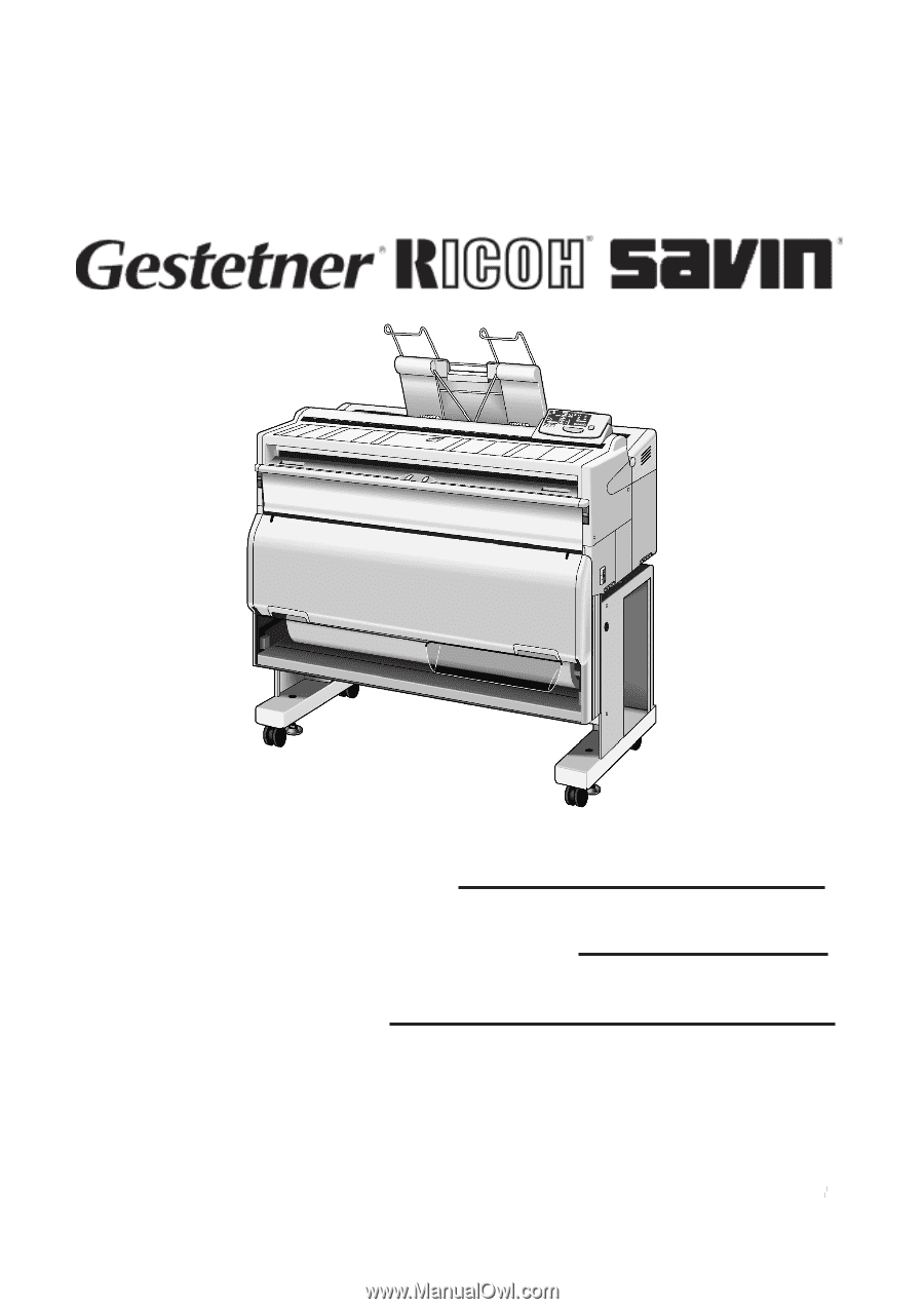
001317MIU
RICOH GROUP COMPANIES
SERVICE MANUAL
A163/A251/A252
B047/B048