Toshiba 50L3400U User's Guide for 40L3400U and 50L3400U Series TV's - Page 26
Connecting a VCR, antenna, cable TV, or camcorder - user manual
 |
View all Toshiba 50L3400U manuals
Add to My Manuals
Save this manual to your list of manuals |
Page 26 highlights
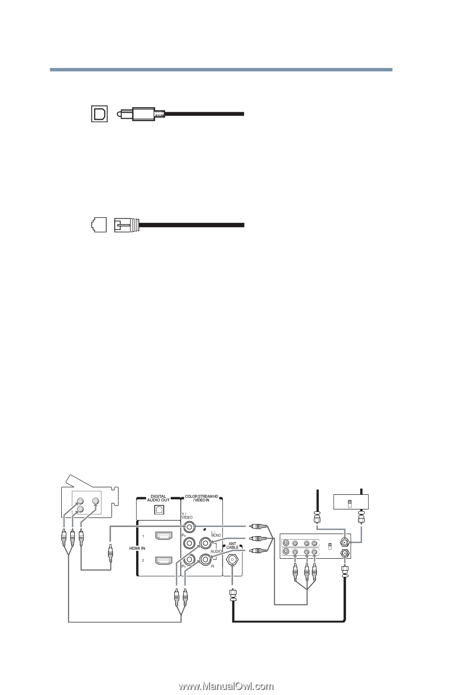
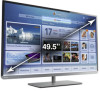
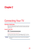
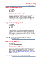
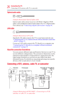
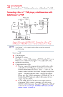
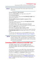
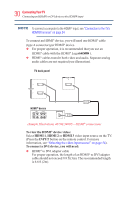
26 ConnectingYourTV Connecting a VCR, antenna, cable TV, or camcorder Optical audio cable (Sample Illustration) Optical audio cable Optical audio cable connect receivers with Dolby® Digital or PCM (pulse-code modulation) optical audio input to the TV's Digital Audio Out terminal, see "Connecting a digital audio system" on page 30. LAN cable (Sample Illustration) LAN cable Standard LAN cable connects the TV to your home network, see "Connecting the TV to a home network with an Internet connection - wired" on page 37. Crossover LAN cable connects the TV directly to a computer, see "Connecting the TV directly to a computer without an Internet connection" on page 35. About the connection illustrations You can connect different types and brands of devices to your TV in several different configurations. The connection illustrations in this manual are representative of typical device connections only. The input/output terminals on your devices may differ from those illustrated herein. For details on connecting and using your specific devices, refer to each device's User's Guide. Connecting a VCR, antenna, cable TV, or camcorder Camcorder AUDIO OUT L R VIDEO TV back panel From cable TV From cable TV or antenna Cable box IN CH 3 CH 4 OUT Stereo VCR VIDEO AUDIO L R IN CH 3 CH 4 OUT L R IN from ANT OUT to TV (Sample Illustration) 40/50L3400U-Connecting to a VCR, antenna, or cable TV, or camcorder
-
 1
1 -
2
-
3
-
4
-
5
-
6
-
7
-
8
-
9
-
10
-
11
-
12
-
13
-
14
-
15
-
16
-
17
-
18
-
19
-
20
-
 21
21 -
 22
22 -
 23
23 -
 24
24 -
 25
25 -
 26
26 -
 27
27 -
 28
28 -
 29
29 -
 30
30 -
 31
31 -
32
-
33
-
34
-
35
-
36
-
37
-
38
-
39
-
40
-
41
-
42
-
43
-
44
-
45
-
46
-
47
-
48
-
49
-
50
-
51
-
52
-
53
-
54
-
55
-
56
-
57
-
58
-
59
-
60
-
61
-
62
-
63
-
64
-
65
-
66
-
67
-
68
-
69
-
70
-
71
-
72
-
73
-
74
-
75
-
76
-
77
-
78
-
79
-
80
-
81
-
82
-
83
-
84
-
85
-
86
-
87
-
88
-
89
-
90
-
91
-
92
-
93
-
94
-
95
-
96
-
97
-
98
-
99
-
100
-
101
-
102
-
103
-
104
-
105
-
106
-
107
-
108
-
109
-
110
-
111
-
112
-
113
-
114
-
115
-
116
-
117
-
118
-
119
-
120
-
121
-
122
-
123
-
124
-
125
-
126
-
127
-
128
-
129
-
130
-
131
-
132
-
133
-
134
-
135
-
136
-
137
-
138
-
139
-
140
-
141
-
142
 |
 |