Yamaha CLP-480 Owner's Manual - Page 83
Attach E and F to D., Attach B., Lay A into position
 |
View all Yamaha CLP-480 manuals
Add to My Manuals
Save this manual to your list of manuals |
Page 83 highlights
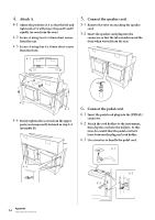
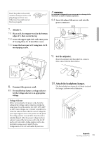
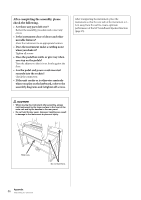
1. Attach E and F to D. 2-3 1-1 Secure D using the four 6 x 20 mm long screws. 1-2 Remove the twist tie from the folded pedal cord. Do not remove the twist tie located next to the hole. Don't discard the twist tie, you'll need it later in step 6. E 1-1 2-4 3. Lay A into position. F Align the screw threads on the bottom of A with D the screw threads of E and F, while gently lowering A into position. 1-2 2. Attach B. 2-1 Insert B between E and F as shown in the illustration. F B D E 15cm F A 15cm E Place your hands at least 15 cm from either end of A when positioning it. CAUTION • Be extra careful not to drop or let your fingers be pinched by the main unit. • Do not hold the main unit in any position other than the position specified above. 2-2 Align and attach B to the front side of D, E and F. 2-3 Secure B using the 4 x 14mm thin screws. * Insert two screws into the smaller holes on the brackets. 2-4 Temporarily secure with 4 x 14mm thin screws. * Insert four screws into the smaller holes on the brackets. Appendix 83 Assembling the Clavinova
-
 1
1 -
2
-
3
-
4
-
5
-
6
-
7
-
8
-
9
-
10
-
11
-
12
-
13
-
14
-
15
-
16
-
17
-
18
-
19
-
20
-
21
-
22
-
23
-
24
-
25
-
26
-
27
-
28
-
29
-
30
-
31
-
32
-
33
-
34
-
35
-
36
-
37
-
38
-
39
-
40
-
41
-
42
-
43
-
44
-
45
-
46
-
47
-
48
-
49
-
50
-
51
-
52
-
53
-
54
-
55
-
56
-
57
-
58
-
59
-
60
-
61
-
62
-
63
-
64
-
65
-
66
-
67
-
68
-
69
-
70
-
71
-
72
-
73
-
74
-
75
-
76
-
77
-
 78
78 -
 79
79 -
 80
80 -
 81
81 -
 82
82 -
 83
83 -
 84
84 -
 85
85 -
 86
86 -
 87
87 -
 88
88 -
89
-
90
-
91
-
92
-
93
-
94
-
95
-
96
 |
 |
