3Ware 7000-2 User Guide - Page 35
3Ware 7000-2 - Escalade RAID Controller Manual
 |
UPC - 693494700022
View all 3Ware 7000-2 manuals
Add to My Manuals
Save this manual to your list of manuals |
Page 35 highlights
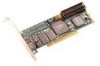
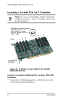
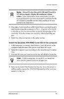
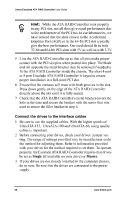
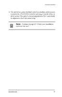
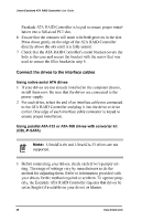
Hardware Installation Note: UltraATA-66, UltraATA-100 and UltraATA133 drives require 40-pin, 80-conductor ribbon cables. These cables have color coded ends. For optimum performance, the blue end must be connected to the ATA RAID Controller and the black end must be connected to the hard drive. 2 One edge of each interface cable should have a colored (usually red) line denoting the conductor to Pin 1. Align the ATA RAID Controller so that the colored line is toward the top edge of the controller. Mate the connectors carefully without bending any pins. 3 Install the other connectors in the same manner. Install the Escalade ATA RAID Controller in the computer 1 If the computer is running, shut it down. Turn off power to the computer and disconnect the power cord from the outlet. 2 Open the computer case according to the manufacturer's instructions. 3 Find the PCI slot you want to use for the ATA RAID Controller. Hint: Cable routing may be easier if you install the ATA RAID Controller next to an open slot. 4 Remove the metal filler bracket for the slot. Save this screw; it will be used to secure the ATA RAID Controller after you have seated it in the slot. www.3ware.com 35
-
 1
1 -
2
-
3
-
4
-
5
-
6
-
7
-
8
-
9
-
10
-
11
-
12
-
13
-
14
-
15
-
16
-
17
-
18
-
19
-
20
-
21
-
22
-
23
-
24
-
25
-
26
-
27
-
28
-
29
-
 30
30 -
 31
31 -
 32
32 -
 33
33 -
 34
34 -
 35
35 -
 36
36 -
 37
37 -
 38
38 -
 39
39 -
 40
40 -
41
-
42
-
43
-
44
-
45
-
46
-
47
-
48
-
49
-
50
-
51
-
52
-
53
-
54
-
55
-
56
-
57
-
58
-
59
-
60
-
61
-
62
-
63
-
64
-
65
-
66
-
67
-
68
-
69
-
70
-
71
-
72
-
73
-
74
-
75
-
76
-
77
-
78
-
79
-
80
-
81
-
82
-
83
-
84
-
85
-
86
-
87
-
88
-
89
-
90
-
91
-
92
-
93
-
94
-
95
-
96
-
97
-
98
-
99
-
100
-
101
-
102
-
103
-
104
-
105
-
106
-
107
-
108
-
109
-
110
-
111
-
112
-
113
-
114
-
115
-
116
-
117
-
118
-
119
-
120
-
121
-
122
-
123
-
124
-
125
-
126
-
127
-
128
-
129
-
130
-
131
-
132
-
133
-
134
-
135
-
136
-
137
-
138
-
139
-
140
-
141
-
142
-
143
-
144
-
145
-
146
-
147
-
148
-
149
-
150
-
151
-
152
-
153
-
154
-
155
-
156
-
157
-
158
-
159
-
160
-
161
-
162
-
163
-
164
-
165
-
166
-
167
-
168
-
169
-
170
-
171
-
172
-
173
-
174
-
175
-
176
-
177
-
178
-
179
-
180
-
181
-
182
-
183
-
184
-
185
-
186
-
187
-
188
-
189
-
190
-
191
-
192
-
193
-
194
-
195
-
196
 |
 |