Dell DX6000G Hardware Owner's Manual - Page 102
Integrated Dell Remote Access Controller 6 (iDRAC6) Enterprise Card (Optional)
 |
View all Dell DX6000G manuals
Add to My Manuals
Save this manual to your list of manuals |
Page 102 highlights
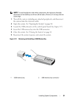
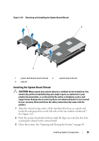
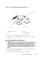
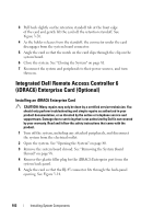
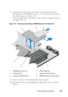
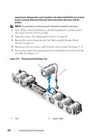
3 Pull back slightly on the retention standoff tab at the front edge of the card and gently lift the card off the retention standoff. See Figure 3-20. 4 As the holder releases from the standoff, the connector under the card disengages from the system board connector. 5 Angle the card so that the notch on the card slips through the clip on the system board. 6 Close the system. See "Closing the System" on page 81. 7 Reconnect the system and peripherals to their power sources, and turn them on. Integrated Dell Remote Access Controller 6 (iDRAC6) Enterprise Card (Optional) Installing an iDRAC6 Enterprise Card CAUTION: Many repairs may only be done by a certified service technician. You should only perform troubleshooting and simple repairs as authorized in your product documentation, or as directed by the online or telephone service and support team. Damage due to servicing that is not authorized by Dell is not covered by your warranty. Read and follow the safety instructions that came with the product. 1 Turn off the system, including any attached peripherals, and disconnect the system from the electrical outlet. 2 Open the system. See "Opening the System" on page 80. 3 Remove the system board shroud. See "Removing the System Board Shroud" on page 98. 4 Remove the plastic filler plug for the iDRAC6 Enterprise port from the system back panel. 5 Angle the card so that the RJ-45 connector fits through the back-panel opening. See Figure 3-14. 102 Installing System Components
-
 1
1 -
2
-
3
-
4
-
5
-
6
-
7
-
8
-
9
-
10
-
11
-
12
-
13
-
14
-
15
-
16
-
17
-
18
-
19
-
20
-
21
-
22
-
23
-
24
-
25
-
26
-
27
-
28
-
29
-
30
-
31
-
32
-
33
-
34
-
35
-
36
-
37
-
38
-
39
-
40
-
41
-
42
-
43
-
44
-
45
-
46
-
47
-
48
-
49
-
50
-
51
-
52
-
53
-
54
-
55
-
56
-
57
-
58
-
59
-
60
-
61
-
62
-
63
-
64
-
65
-
66
-
67
-
68
-
69
-
70
-
71
-
72
-
73
-
74
-
75
-
76
-
77
-
78
-
79
-
80
-
81
-
82
-
83
-
84
-
85
-
86
-
87
-
88
-
89
-
90
-
91
-
92
-
93
-
94
-
95
-
96
-
 97
97 -
 98
98 -
 99
99 -
 100
100 -
 101
101 -
 102
102 -
 103
103 -
 104
104 -
 105
105 -
 106
106 -
 107
107 -
108
-
109
-
110
-
111
-
112
-
113
-
114
-
115
-
116
-
117
-
118
-
119
-
120
-
121
-
122
-
123
-
124
-
125
-
126
-
127
-
128
-
129
-
130
-
131
-
132
-
133
-
134
-
135
-
136
-
137
-
138
-
139
-
140
-
141
-
142
-
143
-
144
-
145
-
146
-
147
-
148
-
149
-
150
-
151
-
152
-
153
-
154
-
155
-
156
-
157
-
158
-
159
-
160
-
161
-
162
-
163
-
164
-
165
-
166
-
167
-
168
-
169
-
170
-
171
-
172
-
173
-
174
 |
 |