Dell DX6000G Hardware Owner's Manual - Page 134
Replacing the Power Distribution Board, SAS Backplane
 |
View all Dell DX6000G manuals
Add to My Manuals
Save this manual to your list of manuals |
Page 134 highlights
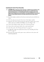
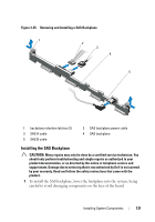
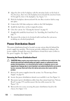
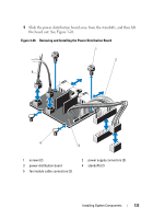
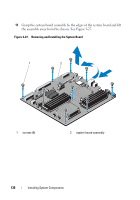
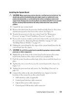
Replacing the Power Distribution Board CAUTION: Many repairs may only be done by a certified service technician. You should only perform troubleshooting and simple repairs as authorized in your product documentation, or as directed by the online or telephone service and support team. Damage due to servicing that is not authorized by Dell is not covered by your warranty. Read and follow the safety instructions that came with the product. 1 Unpack the new power distribution board assembly. 2 Align the power distribution board with the standoffs on the chassis and slide it in place. See Figure 3-26. 3 Install the two screws that secure the power distribution board to the chassis. See Figure 3-26. 4 Connect the power distribution cables to the system board (see "System Board" on page 135)and fan cable connectors to the power distribution board as shown in Figure 3-26. 5 "Removing the Control Panel Assembly on page 126, and "Removing the SAS Backplane" on page 130. 6 Locate the hinged interior catches on either side of the shroud and align and seat the power distribution board cover, rotating it down and over the shroud. See Figure 3-26. 7 Install the power supplies in the system. See "Installing a Power Supply" on page 87. 8 Close the system. See "Closing the System" on page 81. 9 Reconnect the system to its electrical outlet and turn the system on, including any attached peripherals. 134 Installing System Components
-
 1
1 -
2
-
3
-
4
-
5
-
6
-
7
-
8
-
9
-
10
-
11
-
12
-
13
-
14
-
15
-
16
-
17
-
18
-
19
-
20
-
21
-
22
-
23
-
24
-
25
-
26
-
27
-
28
-
29
-
30
-
31
-
32
-
33
-
34
-
35
-
36
-
37
-
38
-
39
-
40
-
41
-
42
-
43
-
44
-
45
-
46
-
47
-
48
-
49
-
50
-
51
-
52
-
53
-
54
-
55
-
56
-
57
-
58
-
59
-
60
-
61
-
62
-
63
-
64
-
65
-
66
-
67
-
68
-
69
-
70
-
71
-
72
-
73
-
74
-
75
-
76
-
77
-
78
-
79
-
80
-
81
-
82
-
83
-
84
-
85
-
86
-
87
-
88
-
89
-
90
-
91
-
92
-
93
-
94
-
95
-
96
-
97
-
98
-
99
-
100
-
101
-
102
-
103
-
104
-
105
-
106
-
107
-
108
-
109
-
110
-
111
-
112
-
113
-
114
-
115
-
116
-
117
-
118
-
119
-
120
-
121
-
122
-
123
-
124
-
125
-
126
-
127
-
128
-
 129
129 -
 130
130 -
 131
131 -
 132
132 -
 133
133 -
 134
134 -
 135
135 -
 136
136 -
 137
137 -
 138
138 -
 139
139 -
140
-
141
-
142
-
143
-
144
-
145
-
146
-
147
-
148
-
149
-
150
-
151
-
152
-
153
-
154
-
155
-
156
-
157
-
158
-
159
-
160
-
161
-
162
-
163
-
164
-
165
-
166
-
167
-
168
-
169
-
170
-
171
-
172
-
173
-
174
 |
 |