Dell DX6000G Hardware Owner's Manual - Page 110
Installing an Optical Drive, System Memory
 |
View all Dell DX6000G manuals
Add to My Manuals
Save this manual to your list of manuals |
Page 110 highlights
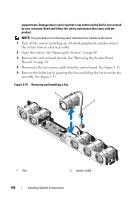
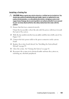
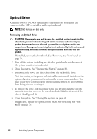
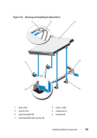
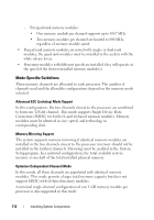
Installing an Optical Drive CAUTION: Many repairs may only be done by a certified service technician. You should only perform troubleshooting and simple repairs as authorized in your product documentation, or as directed by the online or telephone service and support team. Damage due to servicing that is not authorized by Dell is not covered by your warranty. Read and follow the safety instructions that came with the product. 1 If installed, remove the front bezel. See "Removing the Front Bezel" on page 79. 2 Turn off the system, including any attached peripherals, and disconnect the system from its electrical outlet. 3 Open the system. See "Opening the System" on page 80. 4 Align the two notches of the metal standoffs on the chassis with the holes in the drive. See Figure 3-16. 5 Pull the release latch, place the optical drive in position, and release the release latch. 6 Connect the power and data cables to the back of the drive. You must route these cables properly underneath the tabs on the system chassis to prevent them from being pinched or crimped. See Figure 3-1. 7 If not already done, connect the power cable to DVD_PWR and the interface cable to SATA_E on the system board. See Figure 6-1. 8 If applicable, replace the optional front bezel. See "Installing the Front Bezel" on page 79. 9 Reconnect the system and peripherals to their electrical outlets. System Memory Your system supports DDR3 registered DIMMs (RDIMMs) or unbuffered ECC DIMMs (UDIMMs). Single and dual-rank DIMMs can be 1067 MHz or 1333 MHz, and quad-rank DIMMs can be 1067 MHz. The system contains 8 memory sockets split into two sets of four sockets, one set per each processor. Each four-socket set is organized into three channels. Two DIMMs for channel 0 and a single DIMM for channel 1 and 2. The first socket of each channel is marked with white release levers. 110 Installing System Components
-
 1
1 -
2
-
3
-
4
-
5
-
6
-
7
-
8
-
9
-
10
-
11
-
12
-
13
-
14
-
15
-
16
-
17
-
18
-
19
-
20
-
21
-
22
-
23
-
24
-
25
-
26
-
27
-
28
-
29
-
30
-
31
-
32
-
33
-
34
-
35
-
36
-
37
-
38
-
39
-
40
-
41
-
42
-
43
-
44
-
45
-
46
-
47
-
48
-
49
-
50
-
51
-
52
-
53
-
54
-
55
-
56
-
57
-
58
-
59
-
60
-
61
-
62
-
63
-
64
-
65
-
66
-
67
-
68
-
69
-
70
-
71
-
72
-
73
-
74
-
75
-
76
-
77
-
78
-
79
-
80
-
81
-
82
-
83
-
84
-
85
-
86
-
87
-
88
-
89
-
90
-
91
-
92
-
93
-
94
-
95
-
96
-
97
-
98
-
99
-
100
-
101
-
102
-
103
-
104
-
 105
105 -
 106
106 -
 107
107 -
 108
108 -
 109
109 -
 110
110 -
 111
111 -
 112
112 -
 113
113 -
 114
114 -
 115
115 -
116
-
117
-
118
-
119
-
120
-
121
-
122
-
123
-
124
-
125
-
126
-
127
-
128
-
129
-
130
-
131
-
132
-
133
-
134
-
135
-
136
-
137
-
138
-
139
-
140
-
141
-
142
-
143
-
144
-
145
-
146
-
147
-
148
-
149
-
150
-
151
-
152
-
153
-
154
-
155
-
156
-
157
-
158
-
159
-
160
-
161
-
162
-
163
-
164
-
165
-
166
-
167
-
168
-
169
-
170
-
171
-
172
-
173
-
174
 |
 |